Netgear WC7520 WC7520 Reference Manual - Page 123
Table 35., Redundancy Settings
 |
UPC - 606449072969
View all Netgear WC7520 manuals
Add to My Manuals
Save this manual to your list of manuals |
Page 123 highlights
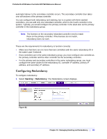
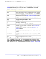
ProSafe 20-AP Wireless Controller WC7520 Reference Manual 2. Configure the settings as explained in Table 35. Table 35. Redundancy Settings Setting Description Enable Redundancy Select this check box to enable the redundancy feature and to unmask the configuration fields that enable you to configure this wireless controller to become part of a redundancy group. Controller Mode Specify if the wireless controller functions as a primary or secondary controller by selecting the Primary or Secondary radio button. Redundancy ID Enter a number (1-255) as the ID for the redundancy group. Controller IP Enter the common IP address that is used by both the primary and secondary controller in this redundancy group. Note: This address is used for controller administration and is assumed by the primary controller; after a failover has occurred, the address is assumed by the secondary controller. Primary IP Enter the IP address of the primary controller (see Configuring IP and VLAN Settings on page 57). Secondary IP Enter the IP address of the secondary controller (see Configuring IP and VLAN Settings on page 57). 3. Click Apply to save your settings. Chapter 10: Managing Stacking and Redundancy | 123
-
 1
1 -
2
-
3
-
4
-
5
-
6
-
7
-
8
-
9
-
10
-
11
-
12
-
13
-
14
-
15
-
16
-
17
-
18
-
19
-
20
-
21
-
22
-
23
-
24
-
25
-
26
-
27
-
28
-
29
-
30
-
31
-
32
-
33
-
34
-
35
-
36
-
37
-
38
-
39
-
40
-
41
-
42
-
43
-
44
-
45
-
46
-
47
-
48
-
49
-
50
-
51
-
52
-
53
-
54
-
55
-
56
-
57
-
58
-
59
-
60
-
61
-
62
-
63
-
64
-
65
-
66
-
67
-
68
-
69
-
70
-
71
-
72
-
73
-
74
-
75
-
76
-
77
-
78
-
79
-
80
-
81
-
82
-
83
-
84
-
85
-
86
-
87
-
88
-
89
-
90
-
91
-
92
-
93
-
94
-
95
-
96
-
97
-
98
-
99
-
100
-
101
-
102
-
103
-
104
-
105
-
106
-
107
-
108
-
109
-
110
-
111
-
112
-
113
-
114
-
115
-
116
-
117
-
 118
118 -
 119
119 -
 120
120 -
 121
121 -
 122
122 -
 123
123 -
 124
124 -
 125
125 -
 126
126 -
 127
127 -
 128
128 -
129
-
130
-
131
-
132
-
133
-
134
-
135
-
136
-
137
-
138
-
139
-
140
-
141
-
142
-
143
-
144
-
145
-
146
-
147
-
148
-
149
-
150
-
151
-
152
-
153
-
154
-
155
-
156
-
157
-
158
-
159
-
160
-
161
-
162
 |
 |