Netgear WC7520 WC7520 Reference Manual - Page 39
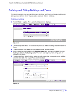
To edit a building, Table 4., Building Name and Floors - support
 |
UPC - 606449072969
View all Netgear WC7520 manuals
Add to My Manuals
Save this manual to your list of manuals |
Page 39 highlights
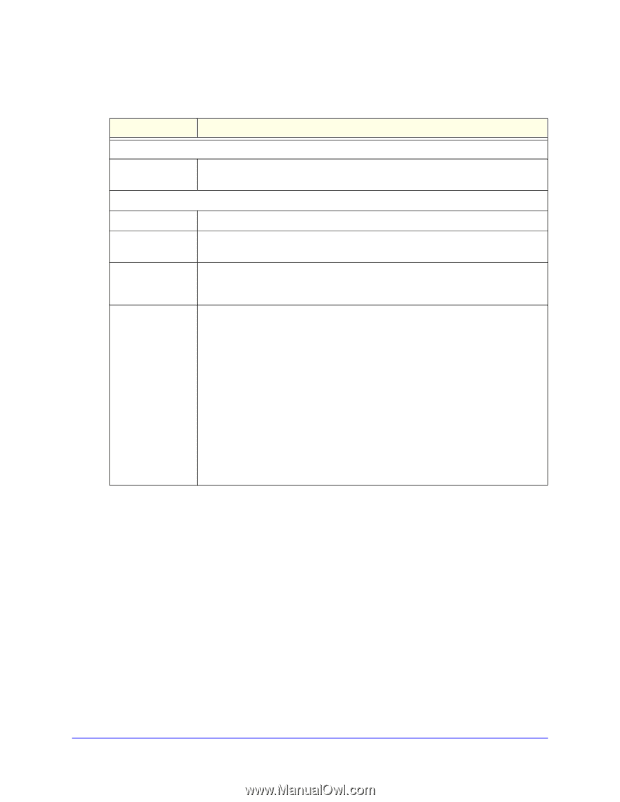
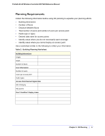
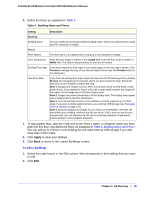
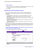
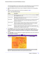
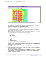
ProSafe 20-AP Wireless Controller WC7520 Reference Manual 6. Define the floors as explained in Table 4. Table 4. Building Name and Floors Setting Building Description Building Name You can modify the previously defined building name, which is an alphanumeric string up to 64 characters in length. Floors Floor Names The floor name is an alphanumeric string up to 64 characters in length. Floor Dimensions Enter the floor length in meters in the Length field; enter the floor width in meters in Width field. The default measurements for both are 40 meters. Existing Floor Map If you have imported a floor map, a very small image of the floor map is shown. Click Preview to enlarge the map. (If you did not import a floor map, the Preview button is not displayed.) New Floor Map If you have an existing floor map, import the map into the RF planning tool by clicking Browse and navigating to the location where you have stored the map. Follow the directions of your browser to import the map. Note 1. Background images must be JPEG format and cannot exceed 2048 x 2048 pixels in size. If you attempt to import a file with a larger pixel footprint, the image will not scale to fit the image area in the floor display area. Note 2. Images are scaled (stretched) to fit the display area. The display area aspect ratio is determined by the floor dimensions. Note 3. The internal flash memory of the wireless controller supports up to 3 floor maps. If you want to define additional floors, use external USB storage (see Managing External Storage on page 107). Note 4. Because background images for your floors are embedded in the XML file that defines your building, minimize the file size of the JPEGs that you use for your backgrounds. You can minimize the file size by selecting maximum compression (lowest quality) in most graphics programs. 7. To add another floor, click the + tab next to the Floor-1 name, or whatever name you have given the first floor, and define the floors as explained in Table 4, Building Name and Floors. You can add up to 6 floors in one building but will need external USB storage if you add more than 3 floor maps. 8. Click Apply to save your settings. 9. Click Back to return to the Layout Buildings screen. To edit a building: 1. Select the radio button in the Edit column that corresponds to the building that you want to edit. 2. Click Edit. Chapter 3: RF Planning | 39
-
 1
1 -
2
-
3
-
4
-
5
-
6
-
7
-
8
-
9
-
10
-
11
-
12
-
13
-
14
-
15
-
16
-
17
-
18
-
19
-
20
-
21
-
22
-
23
-
24
-
25
-
26
-
27
-
28
-
29
-
30
-
31
-
32
-
33
-
 34
34 -
 35
35 -
 36
36 -
 37
37 -
 38
38 -
 39
39 -
 40
40 -
 41
41 -
 42
42 -
 43
43 -
 44
44 -
45
-
46
-
47
-
48
-
49
-
50
-
51
-
52
-
53
-
54
-
55
-
56
-
57
-
58
-
59
-
60
-
61
-
62
-
63
-
64
-
65
-
66
-
67
-
68
-
69
-
70
-
71
-
72
-
73
-
74
-
75
-
76
-
77
-
78
-
79
-
80
-
81
-
82
-
83
-
84
-
85
-
86
-
87
-
88
-
89
-
90
-
91
-
92
-
93
-
94
-
95
-
96
-
97
-
98
-
99
-
100
-
101
-
102
-
103
-
104
-
105
-
106
-
107
-
108
-
109
-
110
-
111
-
112
-
113
-
114
-
115
-
116
-
117
-
118
-
119
-
120
-
121
-
122
-
123
-
124
-
125
-
126
-
127
-
128
-
129
-
130
-
131
-
132
-
133
-
134
-
135
-
136
-
137
-
138
-
139
-
140
-
141
-
142
-
143
-
144
-
145
-
146
-
147
-
148
-
149
-
150
-
151
-
152
-
153
-
154
-
155
-
156
-
157
-
158
-
159
-
160
-
161
-
162
 |
 |