Netgear WC7520 WC7520 Reference Manual - Page 121
Controller Selection Menu, Managing Redundancy
 |
UPC - 606449072969
View all Netgear WC7520 manuals
Add to My Manuals
Save this manual to your list of manuals |
Page 121 highlights
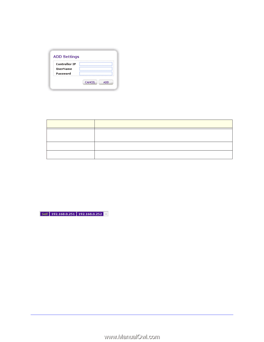
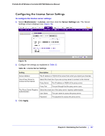
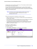
ProSafe 20-AP Wireless Controller WC7520 Reference Manual 2. Click Add to add a wireless controller to the stack. The Add Settings screen displays (see Figure 80). Figure 80. 3. Configure the settings as explained in Table 34. Table 34. Stacking Settings Setting Controller IP Description Enter the IP address of the controller (see Configuring IP and VLAN Settings on page 57). UserName Password Enter the user name to access the controller. Enter the password to access the controller. 4. Click Add. The wireless controller is added to the Stacking table. Controller Selection Menu After you have added one or more wireless controllers to the stack, most screens in the Web management interface display a controller selection menu that lets you select the wireless controller that you want to configure. Figure 81. Click on Self to configure the wireless controller that you have accessed through the Web management interface; click on one of the other two IP addresses to configure that controller in the stack. Managing Redundancy The wireless controller supports 1:1 redundancy with failover. Redundancy is implemented through the use of the Virtual Router Redundancy Protocol (VRRP). You can configure two controllers to form a redundancy group. You then designate one controllers in the redundancy group as the primary controller and the other wireless controller as the secondary controller. If the primary controller fails or is disconnected from the network, an Chapter 10: Managing Stacking and Redundancy | 121
-
 1
1 -
2
-
3
-
4
-
5
-
6
-
7
-
8
-
9
-
10
-
11
-
12
-
13
-
14
-
15
-
16
-
17
-
18
-
19
-
20
-
21
-
22
-
23
-
24
-
25
-
26
-
27
-
28
-
29
-
30
-
31
-
32
-
33
-
34
-
35
-
36
-
37
-
38
-
39
-
40
-
41
-
42
-
43
-
44
-
45
-
46
-
47
-
48
-
49
-
50
-
51
-
52
-
53
-
54
-
55
-
56
-
57
-
58
-
59
-
60
-
61
-
62
-
63
-
64
-
65
-
66
-
67
-
68
-
69
-
70
-
71
-
72
-
73
-
74
-
75
-
76
-
77
-
78
-
79
-
80
-
81
-
82
-
83
-
84
-
85
-
86
-
87
-
88
-
89
-
90
-
91
-
92
-
93
-
94
-
95
-
96
-
97
-
98
-
99
-
100
-
101
-
102
-
103
-
104
-
105
-
106
-
107
-
108
-
109
-
110
-
111
-
112
-
113
-
114
-
115
-
 116
116 -
 117
117 -
 118
118 -
 119
119 -
 120
120 -
 121
121 -
 122
122 -
 123
123 -
 124
124 -
 125
125 -
 126
126 -
127
-
128
-
129
-
130
-
131
-
132
-
133
-
134
-
135
-
136
-
137
-
138
-
139
-
140
-
141
-
142
-
143
-
144
-
145
-
146
-
147
-
148
-
149
-
150
-
151
-
152
-
153
-
154
-
155
-
156
-
157
-
158
-
159
-
160
-
161
-
162
 |
 |