Netgear WC7520 WC7520 Reference Manual - Page 32
System Planning and Deployment Scenarios
 |
UPC - 606449072969
View all Netgear WC7520 manuals
Add to My Manuals
Save this manual to your list of manuals |
Page 32 highlights
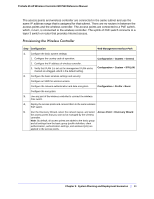
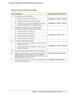
ProSafe 20-AP Wireless Controller WC7520 Reference Manual Provisioning the Wireless Controller Step Configuration Web Management Interface Path 1. For initial discovery and configuration of the access points, temporarily configure management VLAN 100 as an untagged management VLAN on both the wireless controller and the PoE Configuration > System > IP/VLAN switch. 2. Configure the basic system settings: 1. Configure the country code of operation. Configuration > System > General 2. Configure the IP address of wireless controller. 3. Configure the management VLAN as VLAN 100. Configuration > System > IP/VLAN 4. Clear the Untagged Vlan check box. This changes VLAN 1 to a tagged VLAN. 3. Add a DHCP server that uses VLAN 100: 1. Configure the IP address range for VLAN 100. 2. Configure the other DHCP server fields, including the gateway and DNS servers. Configuration > System > DHCP Server 4. Configure the following profiles, and configure network authentication and data encryption for these profiles: 1. A profile with SSID 1 and VLAN 10. 2. A profile with SSID 2 and VLAN 20. Configuration > Profile > Basic 5. Connect the wireless controller to the PoE switch. 6. Before you connect the access points to the PoE switch, verify that the switch ports to which you intend to connect the access points are configured as access ports in management VLAN 100. 7. Deploy the access points and connect them to the designated PoE switch ports. 8. Wait until the access points are up and running, run the Discovery Access Point > Discovery Wizard Wizard, specify the network layout by selecting the Same L2 network radio button, and select the access points that you want to be managed by the wireless controller. Note: By adding the access points to managed list, you enable them to receive an IP address from the DHCP server over management VLAN 100. Chapter 2: System Planning and Deployment Scenarios | 32
-
 1
1 -
2
-
3
-
4
-
5
-
6
-
7
-
8
-
9
-
10
-
11
-
12
-
13
-
14
-
15
-
16
-
17
-
18
-
19
-
20
-
21
-
22
-
23
-
24
-
25
-
26
-
 27
27 -
 28
28 -
 29
29 -
 30
30 -
 31
31 -
 32
32 -
 33
33 -
 34
34 -
 35
35 -
 36
36 -
 37
37 -
38
-
39
-
40
-
41
-
42
-
43
-
44
-
45
-
46
-
47
-
48
-
49
-
50
-
51
-
52
-
53
-
54
-
55
-
56
-
57
-
58
-
59
-
60
-
61
-
62
-
63
-
64
-
65
-
66
-
67
-
68
-
69
-
70
-
71
-
72
-
73
-
74
-
75
-
76
-
77
-
78
-
79
-
80
-
81
-
82
-
83
-
84
-
85
-
86
-
87
-
88
-
89
-
90
-
91
-
92
-
93
-
94
-
95
-
96
-
97
-
98
-
99
-
100
-
101
-
102
-
103
-
104
-
105
-
106
-
107
-
108
-
109
-
110
-
111
-
112
-
113
-
114
-
115
-
116
-
117
-
118
-
119
-
120
-
121
-
122
-
123
-
124
-
125
-
126
-
127
-
128
-
129
-
130
-
131
-
132
-
133
-
134
-
135
-
136
-
137
-
138
-
139
-
140
-
141
-
142
-
143
-
144
-
145
-
146
-
147
-
148
-
149
-
150
-
151
-
152
-
153
-
154
-
155
-
156
-
157
-
158
-
159
-
160
-
161
-
162
 |
 |
