Netgear WC7520 WC7520 Reference Manual - Page 31
Scenario Example 2: Advanced Network with VLANs and SSIDs, Prerequisites
 |
UPC - 606449072969
View all Netgear WC7520 manuals
Add to My Manuals
Save this manual to your list of manuals |
Page 31 highlights
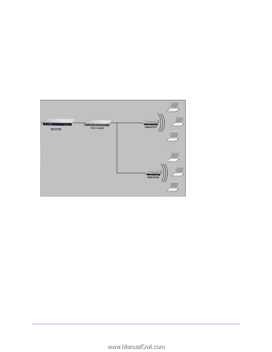
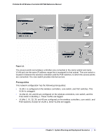
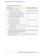
ProSafe 20-AP Wireless Controller WC7520 Reference Manual Scenario Example 2: Advanced Network with VLANs and SSIDs This sample scenario consists of an advanced network with a wireless controller, PoE switch, layer 3 switch or router, access points, and several VLANs and SSIDs. These are the VLANs in the wireless controller system: • VLAN 1, through which you connect to the wireless controller • VLAN 10, which is a client VLAN • VLAN 20, which is a client VLAN • VLAN 100, through which the wireless controller can manage up to 50 access points SSID 1 Client VLAN 10 SSID 2 Client VLAN 20 Figure 11. The access points and wireless controller are connected in the same subnet and same VLAN and use the same IP address range that is assigned for that subnet. There are no routers in between the access points and the wireless controller. The access points are connected to a PoE switch, which, in turn, is connected to the wireless controller. The uplink of the PoE switch connects to a layer 3 switch or router that provides Internet access. Prerequisites This network configuration has the following prerequisites: • VLANs 1, 10, 20, and 100 are tagged VLANs and are configured on both the wireless controller and the PoE switch. • The wireless controller is connected to the PoE switch through default VLAN 1. You manage the wireless controller from a computer over VLAN 1 through the PoE switch • The DHCP server on the wireless controller is configured in management VLAN 100 to enable the access points to receive an IP address through VLAN 100. • The PoE switch port to which the wireless controller is connected is configured as a tagged port to allow tagged traffic from VLAN 1 and VLAN 100. Chapter 2: System Planning and Deployment Scenarios | 31
-
 1
1 -
2
-
3
-
4
-
5
-
6
-
7
-
8
-
9
-
10
-
11
-
12
-
13
-
14
-
15
-
16
-
17
-
18
-
19
-
20
-
21
-
22
-
23
-
24
-
25
-
 26
26 -
 27
27 -
 28
28 -
 29
29 -
 30
30 -
 31
31 -
 32
32 -
 33
33 -
 34
34 -
 35
35 -
 36
36 -
37
-
38
-
39
-
40
-
41
-
42
-
43
-
44
-
45
-
46
-
47
-
48
-
49
-
50
-
51
-
52
-
53
-
54
-
55
-
56
-
57
-
58
-
59
-
60
-
61
-
62
-
63
-
64
-
65
-
66
-
67
-
68
-
69
-
70
-
71
-
72
-
73
-
74
-
75
-
76
-
77
-
78
-
79
-
80
-
81
-
82
-
83
-
84
-
85
-
86
-
87
-
88
-
89
-
90
-
91
-
92
-
93
-
94
-
95
-
96
-
97
-
98
-
99
-
100
-
101
-
102
-
103
-
104
-
105
-
106
-
107
-
108
-
109
-
110
-
111
-
112
-
113
-
114
-
115
-
116
-
117
-
118
-
119
-
120
-
121
-
122
-
123
-
124
-
125
-
126
-
127
-
128
-
129
-
130
-
131
-
132
-
133
-
134
-
135
-
136
-
137
-
138
-
139
-
140
-
141
-
142
-
143
-
144
-
145
-
146
-
147
-
148
-
149
-
150
-
151
-
152
-
153
-
154
-
155
-
156
-
157
-
158
-
159
-
160
-
161
-
162
 |
 |