Netgear WC7520 WC7520 Reference Manual - Page 33
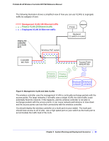
Scenario Example 3: Advanced Network With Redundancy, Four VLANs: VLAN 10, VLAN 20, and VLAN 40
 |
UPC - 606449072969
View all Netgear WC7520 manuals
Add to My Manuals
Save this manual to your list of manuals |
Page 33 highlights
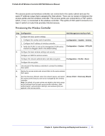
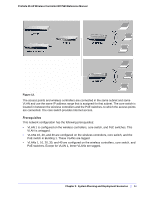
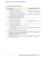
ProSafe 20-AP Wireless Controller WC7520 Reference Manual Step Configuration Web Management Interface Path 9. For each access point on the managed list, clear the Untagged Vlan check box and configure VLAN 100 as the management VLAN. Doing so causes the access points to lose connectivity with the wireless controller. 10. Restore connectivity between the access points and the wireless controller by changing the PoE switch ports to which the access points are connected to tagged ports. (During the discovery process, these switch ports were access ports in management VLAN 100.) Scenario Example 3: Advanced Network With Redundancy This sample scenario consists of an advanced network with one wireless controller, one redundant wireless controller, one core switch, two PoE switches in different buildings, access points, and several VLANs and SSIDs. These are the components in the wireless controller system: • One wireless controller • 50 access points (managed by the wireless controller through management VLAN 1) • One redundant wireless controller • Four VLANs: VLAN 10, VLAN 20, VLAN 30, and VLAN 40 • Three SSIDs: SSID 1, SSID 2, and SSID 3 In this scenario, the VLANs and SSIDs are used to accommodate traffic for different user groups in a school that is spread out over two buildings • Building 1: - SSID 1 in VLAN 10 for staff traffic - SSID 2 in VLAN 20 for middle school students - SSID 3 in VLAN 30 for guests • Building 2: - SSID 1 in VLAN 10 for staff traffic - SSID 2 in VLAN 40 for high school students - SSID 3 in VLAN 30 for guests Chapter 2: System Planning and Deployment Scenarios | 33
-
 1
1 -
2
-
3
-
4
-
5
-
6
-
7
-
8
-
9
-
10
-
11
-
12
-
13
-
14
-
15
-
16
-
17
-
18
-
19
-
20
-
21
-
22
-
23
-
24
-
25
-
26
-
27
-
 28
28 -
 29
29 -
 30
30 -
 31
31 -
 32
32 -
 33
33 -
 34
34 -
 35
35 -
 36
36 -
 37
37 -
 38
38 -
39
-
40
-
41
-
42
-
43
-
44
-
45
-
46
-
47
-
48
-
49
-
50
-
51
-
52
-
53
-
54
-
55
-
56
-
57
-
58
-
59
-
60
-
61
-
62
-
63
-
64
-
65
-
66
-
67
-
68
-
69
-
70
-
71
-
72
-
73
-
74
-
75
-
76
-
77
-
78
-
79
-
80
-
81
-
82
-
83
-
84
-
85
-
86
-
87
-
88
-
89
-
90
-
91
-
92
-
93
-
94
-
95
-
96
-
97
-
98
-
99
-
100
-
101
-
102
-
103
-
104
-
105
-
106
-
107
-
108
-
109
-
110
-
111
-
112
-
113
-
114
-
115
-
116
-
117
-
118
-
119
-
120
-
121
-
122
-
123
-
124
-
125
-
126
-
127
-
128
-
129
-
130
-
131
-
132
-
133
-
134
-
135
-
136
-
137
-
138
-
139
-
140
-
141
-
142
-
143
-
144
-
145
-
146
-
147
-
148
-
149
-
150
-
151
-
152
-
153
-
154
-
155
-
156
-
157
-
158
-
159
-
160
-
161
-
162
 |
 |