Dell PowerEdge 4300 Dell PowerEdge 4300 Systems Installation and Troubleshooti - Page 200
See Accessing the SCSI Backplane Board and Optional PSPB
 |
View all Dell PowerEdge 4300 manuals
Add to My Manuals
Save this manual to your list of manuals |
Page 200 highlights
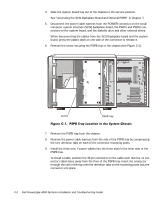
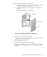
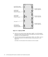
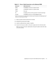
4. Slide the system board tray out of the chassis to the service position. See "Accessing the SCSI Backplane Board and Optional PSPB" in Chapter 7. 5. Disconnect the power cable harness from the POWER connector on the small computer system interface (SCSI) backplane board, the PWR1 and PWR2 connectors on the system board, and the diskette drive and other external drives. When disconnecting the cables from the SCSI backplane board and the system board, press the plastic latch on one side of the connector to release it. 6. Remove the screw securing the PSPB tray to the chassis (see Figure C-1). screw PSPB tray 7. Remove the PSPB tray from the chassis. 8. Remove the power cable harness from the side of the PSPB tray by compressing the two retention tabs on each of the connector mounting posts. 9. Install the three new Y power cables into the three slots in the inner side of the PSPB tray. To install a cable, position the 36-pin connector on the cable such that the J1 connector's label faces away from the floor of the PSPB tray. Insert the connector through the slot in the tray until the retention tabs on the mounting posts lock the connector into place. C-2 Dell PowerEdge 4300 Systems Installation and Troubleshooting Guide
-
 1
1 -
2
-
3
-
4
-
5
-
6
-
7
-
8
-
9
-
10
-
11
-
12
-
13
-
14
-
15
-
16
-
17
-
18
-
19
-
20
-
21
-
22
-
23
-
24
-
25
-
26
-
27
-
28
-
29
-
30
-
31
-
32
-
33
-
34
-
35
-
36
-
37
-
38
-
39
-
40
-
41
-
42
-
43
-
44
-
45
-
46
-
47
-
48
-
49
-
50
-
51
-
52
-
53
-
54
-
55
-
56
-
57
-
58
-
59
-
60
-
61
-
62
-
63
-
64
-
65
-
66
-
67
-
68
-
69
-
70
-
71
-
72
-
73
-
74
-
75
-
76
-
77
-
78
-
79
-
80
-
81
-
82
-
83
-
84
-
85
-
86
-
87
-
88
-
89
-
90
-
91
-
92
-
93
-
94
-
95
-
96
-
97
-
98
-
99
-
100
-
101
-
102
-
103
-
104
-
105
-
106
-
107
-
108
-
109
-
110
-
111
-
112
-
113
-
114
-
115
-
116
-
117
-
118
-
119
-
120
-
121
-
122
-
123
-
124
-
125
-
126
-
127
-
128
-
129
-
130
-
131
-
132
-
133
-
134
-
135
-
136
-
137
-
138
-
139
-
140
-
141
-
142
-
143
-
144
-
145
-
146
-
147
-
148
-
149
-
150
-
151
-
152
-
153
-
154
-
155
-
156
-
157
-
158
-
159
-
160
-
161
-
162
-
163
-
164
-
165
-
166
-
167
-
168
-
169
-
170
-
171
-
172
-
173
-
174
-
175
-
176
-
177
-
178
-
179
-
180
-
181
-
182
-
183
-
184
-
185
-
186
-
187
-
188
-
189
-
190
-
191
-
192
-
193
-
194
-
 195
195 -
 196
196 -
 197
197 -
 198
198 -
 199
199 -
 200
200 -
 201
201 -
 202
202 -
 203
203 -
 204
204 -
 205
205 -
206
-
207
-
208
-
209
-
210
-
211
-
212
-
213
-
214
-
215
-
216
-
217
 |
 |
