Dell PowerEdge 4300 Dell PowerEdge 4300 Systems Installation and Troubleshooti - Page 95
Expansion Card
 |
View all Dell PowerEdge 4300 manuals
Add to My Manuals
Save this manual to your list of manuals |
Page 95 highlights
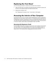
keylock in the latch position door latches (2) expansion-card access door To access the microprocessors or the memory inside the computer, you must remove the interior support panel (see Figure 7-5). To remove the support panel, turn the thumbscrews on the left side of the panel, rotate the panel outward slightly, lift the hinge side of the panel to clear the tabs from the hinge slots, and remove the panel. To access the system board, you must remove all expansion cards in addition to the support panel. For instructions on removing the expansion cards, see "Removing an Expansion Card" in Chapter 8. Checking Inside the Computer 7-7
-
 1
1 -
2
-
3
-
4
-
5
-
6
-
7
-
8
-
9
-
10
-
11
-
12
-
13
-
14
-
15
-
16
-
17
-
18
-
19
-
20
-
21
-
22
-
23
-
24
-
25
-
26
-
27
-
28
-
29
-
30
-
31
-
32
-
33
-
34
-
35
-
36
-
37
-
38
-
39
-
40
-
41
-
42
-
43
-
44
-
45
-
46
-
47
-
48
-
49
-
50
-
51
-
52
-
53
-
54
-
55
-
56
-
57
-
58
-
59
-
60
-
61
-
62
-
63
-
64
-
65
-
66
-
67
-
68
-
69
-
70
-
71
-
72
-
73
-
74
-
75
-
76
-
77
-
78
-
79
-
80
-
81
-
82
-
83
-
84
-
85
-
86
-
87
-
88
-
89
-
 90
90 -
 91
91 -
 92
92 -
 93
93 -
 94
94 -
 95
95 -
 96
96 -
 97
97 -
 98
98 -
 99
99 -
 100
100 -
101
-
102
-
103
-
104
-
105
-
106
-
107
-
108
-
109
-
110
-
111
-
112
-
113
-
114
-
115
-
116
-
117
-
118
-
119
-
120
-
121
-
122
-
123
-
124
-
125
-
126
-
127
-
128
-
129
-
130
-
131
-
132
-
133
-
134
-
135
-
136
-
137
-
138
-
139
-
140
-
141
-
142
-
143
-
144
-
145
-
146
-
147
-
148
-
149
-
150
-
151
-
152
-
153
-
154
-
155
-
156
-
157
-
158
-
159
-
160
-
161
-
162
-
163
-
164
-
165
-
166
-
167
-
168
-
169
-
170
-
171
-
172
-
173
-
174
-
175
-
176
-
177
-
178
-
179
-
180
-
181
-
182
-
183
-
184
-
185
-
186
-
187
-
188
-
189
-
190
-
191
-
192
-
193
-
194
-
195
-
196
-
197
-
198
-
199
-
200
-
201
-
202
-
203
-
204
-
205
-
206
-
207
-
208
-
209
-
210
-
211
-
212
-
213
-
214
-
215
-
216
-
217
 |
 |

Checking Inside the Computer
7-7
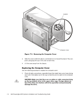
)LJXUH±¼¶¹µ±±$FFHVVLQJ±WKH±([SDQVLRQ±&DUGV
$FFHVVLQJ±WKH±0LFURSURFHVVRUV³±0HPRU\³±RU±6\VWHP±%RDUG
To access the microprocessors or the memory inside the computer, you must remove
the interior support panel (see Figure 7-5). To remove the support panel, turn the
thumbscrews on the left side of the panel, rotate the panel outward slightly, lift the
hinge side of the panel to clear the tabs from the hinge slots, and remove the panel.
To access the system board, you must remove all expansion cards in addition to the
support panel. For instructions on removing the expansion cards, see “Removing an
Expansion Card” in Chapter 8.
expansion-card access door
keylock in the
latch position
door
latches (2)