Dell PowerEdge 4300 Dell PowerEdge 4300 Systems Installation and Troubleshooti - Page 201
Upgrading the Computer With Additional Power Supplies, PSPB tray, captive screw
 |
View all Dell PowerEdge 4300 manuals
Add to My Manuals
Save this manual to your list of manuals |
Page 201 highlights
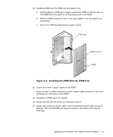
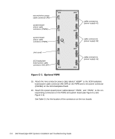
10. Install the PSPB onto the PSPB tray (see Figure C-2): a. While holding the PSPB by its edges, position the PSPB so that the tabs on the PSPB tray fit through the corresponding slots in the PSPB. b. Slide the PSPB toward the front of the tray a quarter of an inch (about one centimeter). c. Secure the PSPB by tightening the captive screw. PSPB tray captive screw PSPB 11. Connect the three Y power cables to the PSPB. Attach the pair of cables leading from each Y power cable connector to the corresponding two connectors on the PSPB. 12. Reinstall the PSPB tray in the chassis. 13. Secure the tray with the screw you removed in step 6. 14. Attach the 4-conductor power cable to the external-drive power cable connector (labeled "FD") on the PSPB (see Figure C-3) and to the drives in the external drive bays. Upgrading the Computer With Additional Power Supplies C-3
-
 1
1 -
2
-
3
-
4
-
5
-
6
-
7
-
8
-
9
-
10
-
11
-
12
-
13
-
14
-
15
-
16
-
17
-
18
-
19
-
20
-
21
-
22
-
23
-
24
-
25
-
26
-
27
-
28
-
29
-
30
-
31
-
32
-
33
-
34
-
35
-
36
-
37
-
38
-
39
-
40
-
41
-
42
-
43
-
44
-
45
-
46
-
47
-
48
-
49
-
50
-
51
-
52
-
53
-
54
-
55
-
56
-
57
-
58
-
59
-
60
-
61
-
62
-
63
-
64
-
65
-
66
-
67
-
68
-
69
-
70
-
71
-
72
-
73
-
74
-
75
-
76
-
77
-
78
-
79
-
80
-
81
-
82
-
83
-
84
-
85
-
86
-
87
-
88
-
89
-
90
-
91
-
92
-
93
-
94
-
95
-
96
-
97
-
98
-
99
-
100
-
101
-
102
-
103
-
104
-
105
-
106
-
107
-
108
-
109
-
110
-
111
-
112
-
113
-
114
-
115
-
116
-
117
-
118
-
119
-
120
-
121
-
122
-
123
-
124
-
125
-
126
-
127
-
128
-
129
-
130
-
131
-
132
-
133
-
134
-
135
-
136
-
137
-
138
-
139
-
140
-
141
-
142
-
143
-
144
-
145
-
146
-
147
-
148
-
149
-
150
-
151
-
152
-
153
-
154
-
155
-
156
-
157
-
158
-
159
-
160
-
161
-
162
-
163
-
164
-
165
-
166
-
167
-
168
-
169
-
170
-
171
-
172
-
173
-
174
-
175
-
176
-
177
-
178
-
179
-
180
-
181
-
182
-
183
-
184
-
185
-
186
-
187
-
188
-
189
-
190
-
191
-
192
-
193
-
194
-
195
-
 196
196 -
 197
197 -
 198
198 -
 199
199 -
 200
200 -
 201
201 -
 202
202 -
 203
203 -
 204
204 -
 205
205 -
 206
206 -
207
-
208
-
209
-
210
-
211
-
212
-
213
-
214
-
215
-
216
-
217
 |
 |
