Lexmark X644E Service Manual - Page 171
CAUTION, Fuser assembly. See
 |
UPC - 734646093156
View all Lexmark X644E manuals
Add to My Manuals
Save this manual to your list of manuals |
Page 171 highlights
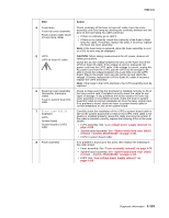
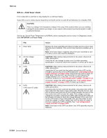
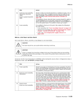
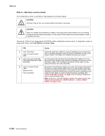
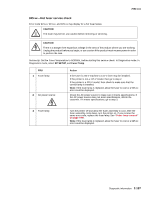
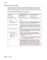
7002-xxx FRU 4 Fuser lamp Fuser top cover assembly Fuser connect cable (fuser to fuser lamp cable) 5 LVPS LVPS to fuser AC cable 6 Fuser top cover assembly (thermistor, thermistor cable) Fuser to system board DC cable 7 Error code 920.06 displayed LVPS System board System board to LVPS cable 8 Fuser assembly Action Check continuity of the fuser to fuser AC cable, fuser top cover assembly, and fuser lamp by checking the continuity between the two pins on the fuser lamp AC cable connector: • If there is continuity, go to step 5. • If there is no continuity, check the continuity of the fuser to fuser lamp AC cable. If incorrect, replace the lamp, if incorrect, replace the fuser top cover assembly. Note: If the fuser lamp is replaced, allow the fuser assembly to cool or a 925.xx error may be displayed. CAUTION: When taking measurements for AC power, observe all safety precautions. Check the AC line voltage between the pins on the fuser end of the LPVS to fuser AC cable. If the voltage is correct, unplug the AC power cord from the LVPS cable. If the voltage is correct, unplug the AC power cord from the LVPS, pull the LVPS out far enough to be able to check the voltage between CN-1 and CN1-3 on the LVPS board. Plug in the power cord, turn the printer on and check the voltage. If correct, replace the LVPS to fuser AC cable; if incorrect, replace the LVPS assembly. Note: If the fuses in the LVPS are blown, the LVPS assembly must be replaced. Check to make sure that the thermistor is installed correctly to J5 on the fuser control card. If installed correctly check the cable for any signs of damage. If any problems are found, replace the fuser top cover assembly. If no problem is found, check the fuser to system board DC cable for correct installation at J1 on the fuser control card. If no problem is found, check the fuser to system board cable for correct installation at J10 on the system board. Carefully check the installation of the LVPS to system board cable to J27 on the system board and to CN2 on the LVPS. If the cable is not seated or installed properly, reseat the cable and retry the printer. If the cable is installed correctly, replace the following FRUs in the order shown: • LVPS assembly. See "Low voltage power supply removal" on page 4-109. • System board assembly. See "System board and inner shield removal -models X644e/X646e" on page 4-131. • LVPS to system board cable. If no problem is found up to this point, then replace the following in the order shown: • Fuser assembly. See "Fuser assembly removal" on page 4-79. • System board assembly. See "System board and inner shield removal -models X644e/X646e" on page 4-131. • LVPS. See "Low voltage power supply removal" on page 4-109. Diagnostic information 2-133
-
 1
1 -
2
-
3
-
4
-
5
-
6
-
7
-
8
-
9
-
10
-
11
-
12
-
13
-
14
-
15
-
16
-
17
-
18
-
19
-
20
-
21
-
22
-
23
-
24
-
25
-
26
-
27
-
28
-
29
-
30
-
31
-
32
-
33
-
34
-
35
-
36
-
37
-
38
-
39
-
40
-
41
-
42
-
43
-
44
-
45
-
46
-
47
-
48
-
49
-
50
-
51
-
52
-
53
-
54
-
55
-
56
-
57
-
58
-
59
-
60
-
61
-
62
-
63
-
64
-
65
-
66
-
67
-
68
-
69
-
70
-
71
-
72
-
73
-
74
-
75
-
76
-
77
-
78
-
79
-
80
-
81
-
82
-
83
-
84
-
85
-
86
-
87
-
88
-
89
-
90
-
91
-
92
-
93
-
94
-
95
-
96
-
97
-
98
-
99
-
100
-
101
-
102
-
103
-
104
-
105
-
106
-
107
-
108
-
109
-
110
-
111
-
112
-
113
-
114
-
115
-
116
-
117
-
118
-
119
-
120
-
121
-
122
-
123
-
124
-
125
-
126
-
127
-
128
-
129
-
130
-
131
-
132
-
133
-
134
-
135
-
136
-
137
-
138
-
139
-
140
-
141
-
142
-
143
-
144
-
145
-
146
-
147
-
148
-
149
-
150
-
151
-
152
-
153
-
154
-
155
-
156
-
157
-
158
-
159
-
160
-
161
-
162
-
163
-
164
-
165
-
 166
166 -
 167
167 -
 168
168 -
 169
169 -
 170
170 -
 171
171 -
 172
172 -
 173
173 -
 174
174 -
 175
175 -
 176
176 -
177
-
178
-
179
-
180
-
181
-
182
-
183
-
184
-
185
-
186
-
187
-
188
-
189
-
190
-
191
-
192
-
193
-
194
-
195
-
196
-
197
-
198
-
199
-
200
-
201
-
202
-
203
-
204
-
205
-
206
-
207
-
208
-
209
-
210
-
211
-
212
-
213
-
214
-
215
-
216
-
217
-
218
-
219
-
220
-
221
-
222
-
223
-
224
-
225
-
226
-
227
-
228
-
229
-
230
-
231
-
232
-
233
-
234
-
235
-
236
-
237
-
238
-
239
-
240
-
241
-
242
-
243
-
244
-
245
-
246
-
247
-
248
-
249
-
250
-
251
-
252
-
253
-
254
-
255
-
256
-
257
-
258
-
259
-
260
-
261
-
262
-
263
-
264
-
265
-
266
-
267
-
268
-
269
-
270
-
271
-
272
-
273
-
274
-
275
-
276
-
277
-
278
-
279
-
280
-
281
-
282
-
283
-
284
-
285
-
286
-
287
-
288
-
289
-
290
-
291
-
292
-
293
-
294
-
295
-
296
-
297
-
298
-
299
-
300
-
301
-
302
-
303
-
304
-
305
-
306
-
307
-
308
-
309
-
310
-
311
-
312
-
313
-
314
-
315
-
316
-
317
-
318
-
319
-
320
-
321
-
322
-
323
-
324
-
325
-
326
-
327
-
328
-
329
-
330
-
331
-
332
-
333
-
334
-
335
-
336
-
337
-
338
-
339
-
340
-
341
-
342
-
343
-
344
-
345
-
346
-
347
-
348
-
349
-
350
-
351
-
352
-
353
-
354
-
355
-
356
-
357
-
358
-
359
-
360
-
361
-
362
-
363
-
364
-
365
-
366
-
367
-
368
-
369
-
370
-
371
-
372
-
373
-
374
-
375
-
376
-
377
-
378
-
379
-
380
-
381
-
382
-
383
-
384
-
385
-
386
-
387
-
388
-
389
-
390
-
391
-
392
-
393
-
394
-
395
-
396
-
397
-
398
-
399
-
400
-
401
-
402
-
403
-
404
-
405
-
406
-
407
-
408
-
409
-
410
-
411
-
412
-
413
-
414
-
415
-
416
-
417
-
418
-
419
-
420
-
421
-
422
-
423
-
424
-
425
-
426
-
427
-
428
-
429
-
430
-
431
-
432
-
433
-
434
-
435
-
436
-
437
-
438
-
439
-
440
-
441
-
442
-
443
-
444
-
445
-
446
-
447
-
448
-
449
-
450
-
451
-
452
-
453
-
454
-
455
-
456
-
457
-
458
-
459
-
460
-
461
-
462
-
463
-
464
-
465
-
466
-
467
-
468
-
469
-
470
-
471
-
472
-
473
-
474
-
475
-
476
-
477
-
478
-
479
-
480
-
481
-
482
-
483
-
484
-
485
-
486
-
487
-
488
-
489
-
490
-
491
-
492
-
493
-
494
-
495
-
496
-
497
-
498
-
499
-
500
-
501
-
502
-
503
-
504
-
505
-
506
-
507
-
508
-
509
-
510
-
511
-
512
-
513
-
514
-
515
-
516
-
517
-
518
-
519
-
520
-
521
-
522
-
523
-
524
-
525
 |
 |