Lexmark X644E Service Manual - Page 190
LCD touchscreen display lights up, icons displayed, but it does not work when, touched
 |
UPC - 734646093156
View all Lexmark X644E manuals
Add to My Manuals
Save this manual to your list of manuals |
Page 190 highlights
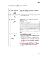
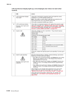
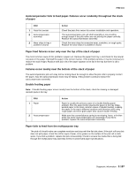
7002-xxx LCD touchscreen display lights up, icons displayed, but it does not work when touched. FRU 1 LCD touchscreen display/ 4-pin cable 2 LCD touchscreen display Operator panel right cover assembly 3 Inverter card 4 Inverter card assembly Operator panel right cover assembly Action Check the 4-pin display to operator panel card cable for correct installation to J3 on the operator panel card. Note: This cable is a short ribbon cable that can easily become disconnected from J3 on the operator panel card. If the cable is properly installed, go to step 2. If the cable is connected properly to J3, replace the operator panel right cover assembly. See "Operator panel right cover assembly removal" on page 4-64. If this does not fix the problem, replace the LCD touchscreen display assembly. See "LCD touchscreen removal-models X644e and X646e" on page 4-67. Check the voltages on CN1-1 and CN1-2. They should measure approximately +12 V dc. Inverter card Connector Cn1 (to operator panel card) Pin number Voltage CN1-Pin 1 +12 V dc CN1-Pin 2 +125 V dc CN1-Pin 3 0 V dc CN1-Pin 4 0 V dc CN1-Pin 5 0 V dc (screen light Z) +4-5 V dc (screen dark) CN1-Pin 6 0-+5 V dc BRIGHTNESS ADJUST CN1-Pin 7 0 V dc CN1-Pin 8 0 V dc If incorrect, replace the operator panel card assembly. If correct, go to step 4. Enter the following Menus, Settings, General Settings, and Screen Brightness on the touchscreen display. • Enter 22 on the touchscreen display, and Submit the new setting. Measure the voltage at CN1-5. The voltage should measure approximately 0 to +1.5 V dc. • Enter 50 on the touchscreen display, and Submit. Measure the voltage at CN1-5. The voltage should measure approximately +2.7 V dc. • Enter 100 on the touchscreen display, and Submit. Measure the voltage at CN1-5. The voltage should measure approximately +5.0 V dc. If the voltages do not change when going from 22 to 100 on the display, replace the operator panel right cover assembly. See "Operator panel right cover assembly removal" on page 4-64. If this does not fix the problem, replace the LCD inverter card assembly. See "LCD inverter card assembly removal" on page 4-108. 2-152 Service Manual
-
 1
1 -
2
-
3
-
4
-
5
-
6
-
7
-
8
-
9
-
10
-
11
-
12
-
13
-
14
-
15
-
16
-
17
-
18
-
19
-
20
-
21
-
22
-
23
-
24
-
25
-
26
-
27
-
28
-
29
-
30
-
31
-
32
-
33
-
34
-
35
-
36
-
37
-
38
-
39
-
40
-
41
-
42
-
43
-
44
-
45
-
46
-
47
-
48
-
49
-
50
-
51
-
52
-
53
-
54
-
55
-
56
-
57
-
58
-
59
-
60
-
61
-
62
-
63
-
64
-
65
-
66
-
67
-
68
-
69
-
70
-
71
-
72
-
73
-
74
-
75
-
76
-
77
-
78
-
79
-
80
-
81
-
82
-
83
-
84
-
85
-
86
-
87
-
88
-
89
-
90
-
91
-
92
-
93
-
94
-
95
-
96
-
97
-
98
-
99
-
100
-
101
-
102
-
103
-
104
-
105
-
106
-
107
-
108
-
109
-
110
-
111
-
112
-
113
-
114
-
115
-
116
-
117
-
118
-
119
-
120
-
121
-
122
-
123
-
124
-
125
-
126
-
127
-
128
-
129
-
130
-
131
-
132
-
133
-
134
-
135
-
136
-
137
-
138
-
139
-
140
-
141
-
142
-
143
-
144
-
145
-
146
-
147
-
148
-
149
-
150
-
151
-
152
-
153
-
154
-
155
-
156
-
157
-
158
-
159
-
160
-
161
-
162
-
163
-
164
-
165
-
166
-
167
-
168
-
169
-
170
-
171
-
172
-
173
-
174
-
175
-
176
-
177
-
178
-
179
-
180
-
181
-
182
-
183
-
184
-
 185
185 -
 186
186 -
 187
187 -
 188
188 -
 189
189 -
 190
190 -
 191
191 -
 192
192 -
 193
193 -
 194
194 -
 195
195 -
196
-
197
-
198
-
199
-
200
-
201
-
202
-
203
-
204
-
205
-
206
-
207
-
208
-
209
-
210
-
211
-
212
-
213
-
214
-
215
-
216
-
217
-
218
-
219
-
220
-
221
-
222
-
223
-
224
-
225
-
226
-
227
-
228
-
229
-
230
-
231
-
232
-
233
-
234
-
235
-
236
-
237
-
238
-
239
-
240
-
241
-
242
-
243
-
244
-
245
-
246
-
247
-
248
-
249
-
250
-
251
-
252
-
253
-
254
-
255
-
256
-
257
-
258
-
259
-
260
-
261
-
262
-
263
-
264
-
265
-
266
-
267
-
268
-
269
-
270
-
271
-
272
-
273
-
274
-
275
-
276
-
277
-
278
-
279
-
280
-
281
-
282
-
283
-
284
-
285
-
286
-
287
-
288
-
289
-
290
-
291
-
292
-
293
-
294
-
295
-
296
-
297
-
298
-
299
-
300
-
301
-
302
-
303
-
304
-
305
-
306
-
307
-
308
-
309
-
310
-
311
-
312
-
313
-
314
-
315
-
316
-
317
-
318
-
319
-
320
-
321
-
322
-
323
-
324
-
325
-
326
-
327
-
328
-
329
-
330
-
331
-
332
-
333
-
334
-
335
-
336
-
337
-
338
-
339
-
340
-
341
-
342
-
343
-
344
-
345
-
346
-
347
-
348
-
349
-
350
-
351
-
352
-
353
-
354
-
355
-
356
-
357
-
358
-
359
-
360
-
361
-
362
-
363
-
364
-
365
-
366
-
367
-
368
-
369
-
370
-
371
-
372
-
373
-
374
-
375
-
376
-
377
-
378
-
379
-
380
-
381
-
382
-
383
-
384
-
385
-
386
-
387
-
388
-
389
-
390
-
391
-
392
-
393
-
394
-
395
-
396
-
397
-
398
-
399
-
400
-
401
-
402
-
403
-
404
-
405
-
406
-
407
-
408
-
409
-
410
-
411
-
412
-
413
-
414
-
415
-
416
-
417
-
418
-
419
-
420
-
421
-
422
-
423
-
424
-
425
-
426
-
427
-
428
-
429
-
430
-
431
-
432
-
433
-
434
-
435
-
436
-
437
-
438
-
439
-
440
-
441
-
442
-
443
-
444
-
445
-
446
-
447
-
448
-
449
-
450
-
451
-
452
-
453
-
454
-
455
-
456
-
457
-
458
-
459
-
460
-
461
-
462
-
463
-
464
-
465
-
466
-
467
-
468
-
469
-
470
-
471
-
472
-
473
-
474
-
475
-
476
-
477
-
478
-
479
-
480
-
481
-
482
-
483
-
484
-
485
-
486
-
487
-
488
-
489
-
490
-
491
-
492
-
493
-
494
-
495
-
496
-
497
-
498
-
499
-
500
-
501
-
502
-
503
-
504
-
505
-
506
-
507
-
508
-
509
-
510
-
511
-
512
-
513
-
514
-
515
-
516
-
517
-
518
-
519
-
520
-
521
-
522
-
523
-
524
-
525
 |
 |