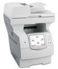
Lexmark X644E Service Manual - Page 192
Operator panel Help and Home buttons service check-model X642e
 |
UPC - 734646093156
View all Lexmark X644E manuals
Add to My Manuals
Save this manual to your list of manuals |
Page 192 highlights
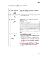
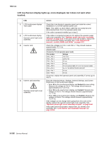
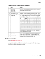
7002-xxx Operator panel Help and Home buttons service check-model X642e Note: Run the Button Test from the Diagnostics Menu to determine if the buttons are operating properly. See "Button Test" on page 3-8. FRU 1 UICC card #1 to UICC card #2 cable (UICC 4-pin cable) 2 UICC card #1 to UICC card #2 cable (UICC 4-pin cable) 3 Bezel assembly Action Check the UICC 4-pin cable for correct installation to J15 on UICC card #1 and to J1 on UICC card #2. If installed correctly, go to step 2. Check continuity of the UICC 4-pin cable. If correct, go to step 3. If incorrect, replace the cable. Replace the bezel assembly which has UICC card #2 attached. If this does not fix the problem, replace the operator panel right cover assembly. See "Operator panel right cover assembly removal" on page 4-64. Operator panel Menu button service check-model X642e Note: Run the Button Test from the Diagnostics Menu and check the button for proper operation. See "Button Test" on page 3-8. FRU 1 UICC card # 1 to UICC card #3 cable (UICC 8-pin cable) 2 UICC card #1 to UICC card #3 cable (UICC 8-pin cable) 3 Operator panel left cover assembly Action Check the cable for correct installation to J1 on UICC card #3 and to J14 on UICC card # 1 (operator panel card). If installed correctly, go to step 2. Check continuity of the UICC 8-pin cable. If correct, go to step 3. If incorrect, replace the cable. Replace the operator panel left cover assembly. See "Operator panel left cover assembly removal" on page 4-61. If this does not fix the problem replace the operator panel right cover assembly. See "Operator panel right cover assembly removal" on page 4-64. Operator panel right cover assembly service check Operator panel LED off. FRU 1 UICC 18-pin operator panel to scanner control card cable 2 UICC 18-pin operator panel to scanner control card cable Scanner control card 3 Scanner control card Action Check to make sure the cable is correctly connected to J10 on the operator panel card and to J15 on the scanner control card. If the cable is correctly connected, go to step 2. Check the cable for any signs of damaged or bent pins. If incorrect, replace the cable. If correct, go to step 3. Measure the voltage at J15-17 and J15-18. The voltage should measure approximately +24 V dc. If incorrect, replace the scanner control card. See "Scanner control card removal" on page 4-48. If correct, replace the operator panel right cover assembly. See "Operator panel right cover assembly removal" on page 4-64. 2-154 Service Manual
-
 1
1 -
2
-
3
-
4
-
5
-
6
-
7
-
8
-
9
-
10
-
11
-
12
-
13
-
14
-
15
-
16
-
17
-
18
-
19
-
20
-
21
-
22
-
23
-
24
-
25
-
26
-
27
-
28
-
29
-
30
-
31
-
32
-
33
-
34
-
35
-
36
-
37
-
38
-
39
-
40
-
41
-
42
-
43
-
44
-
45
-
46
-
47
-
48
-
49
-
50
-
51
-
52
-
53
-
54
-
55
-
56
-
57
-
58
-
59
-
60
-
61
-
62
-
63
-
64
-
65
-
66
-
67
-
68
-
69
-
70
-
71
-
72
-
73
-
74
-
75
-
76
-
77
-
78
-
79
-
80
-
81
-
82
-
83
-
84
-
85
-
86
-
87
-
88
-
89
-
90
-
91
-
92
-
93
-
94
-
95
-
96
-
97
-
98
-
99
-
100
-
101
-
102
-
103
-
104
-
105
-
106
-
107
-
108
-
109
-
110
-
111
-
112
-
113
-
114
-
115
-
116
-
117
-
118
-
119
-
120
-
121
-
122
-
123
-
124
-
125
-
126
-
127
-
128
-
129
-
130
-
131
-
132
-
133
-
134
-
135
-
136
-
137
-
138
-
139
-
140
-
141
-
142
-
143
-
144
-
145
-
146
-
147
-
148
-
149
-
150
-
151
-
152
-
153
-
154
-
155
-
156
-
157
-
158
-
159
-
160
-
161
-
162
-
163
-
164
-
165
-
166
-
167
-
168
-
169
-
170
-
171
-
172
-
173
-
174
-
175
-
176
-
177
-
178
-
179
-
180
-
181
-
182
-
183
-
184
-
185
-
186
-
 187
187 -
 188
188 -
 189
189 -
 190
190 -
 191
191 -
 192
192 -
 193
193 -
 194
194 -
 195
195 -
 196
196 -
 197
197 -
198
-
199
-
200
-
201
-
202
-
203
-
204
-
205
-
206
-
207
-
208
-
209
-
210
-
211
-
212
-
213
-
214
-
215
-
216
-
217
-
218
-
219
-
220
-
221
-
222
-
223
-
224
-
225
-
226
-
227
-
228
-
229
-
230
-
231
-
232
-
233
-
234
-
235
-
236
-
237
-
238
-
239
-
240
-
241
-
242
-
243
-
244
-
245
-
246
-
247
-
248
-
249
-
250
-
251
-
252
-
253
-
254
-
255
-
256
-
257
-
258
-
259
-
260
-
261
-
262
-
263
-
264
-
265
-
266
-
267
-
268
-
269
-
270
-
271
-
272
-
273
-
274
-
275
-
276
-
277
-
278
-
279
-
280
-
281
-
282
-
283
-
284
-
285
-
286
-
287
-
288
-
289
-
290
-
291
-
292
-
293
-
294
-
295
-
296
-
297
-
298
-
299
-
300
-
301
-
302
-
303
-
304
-
305
-
306
-
307
-
308
-
309
-
310
-
311
-
312
-
313
-
314
-
315
-
316
-
317
-
318
-
319
-
320
-
321
-
322
-
323
-
324
-
325
-
326
-
327
-
328
-
329
-
330
-
331
-
332
-
333
-
334
-
335
-
336
-
337
-
338
-
339
-
340
-
341
-
342
-
343
-
344
-
345
-
346
-
347
-
348
-
349
-
350
-
351
-
352
-
353
-
354
-
355
-
356
-
357
-
358
-
359
-
360
-
361
-
362
-
363
-
364
-
365
-
366
-
367
-
368
-
369
-
370
-
371
-
372
-
373
-
374
-
375
-
376
-
377
-
378
-
379
-
380
-
381
-
382
-
383
-
384
-
385
-
386
-
387
-
388
-
389
-
390
-
391
-
392
-
393
-
394
-
395
-
396
-
397
-
398
-
399
-
400
-
401
-
402
-
403
-
404
-
405
-
406
-
407
-
408
-
409
-
410
-
411
-
412
-
413
-
414
-
415
-
416
-
417
-
418
-
419
-
420
-
421
-
422
-
423
-
424
-
425
-
426
-
427
-
428
-
429
-
430
-
431
-
432
-
433
-
434
-
435
-
436
-
437
-
438
-
439
-
440
-
441
-
442
-
443
-
444
-
445
-
446
-
447
-
448
-
449
-
450
-
451
-
452
-
453
-
454
-
455
-
456
-
457
-
458
-
459
-
460
-
461
-
462
-
463
-
464
-
465
-
466
-
467
-
468
-
469
-
470
-
471
-
472
-
473
-
474
-
475
-
476
-
477
-
478
-
479
-
480
-
481
-
482
-
483
-
484
-
485
-
486
-
487
-
488
-
489
-
490
-
491
-
492
-
493
-
494
-
495
-
496
-
497
-
498
-
499
-
500
-
501
-
502
-
503
-
504
-
505
-
506
-
507
-
508
-
509
-
510
-
511
-
512
-
513
-
514
-
515
-
516
-
517
-
518
-
519
-
520
-
521
-
522
-
523
-
524
-
525
 |
 |