Lexmark X644E Service Manual - Page 184
Input sensor service check, displays when the high-capacity feeder input tray is full or has
 |
UPC - 734646093156
View all Lexmark X644E manuals
Add to My Manuals
Save this manual to your list of manuals |
Page 184 highlights
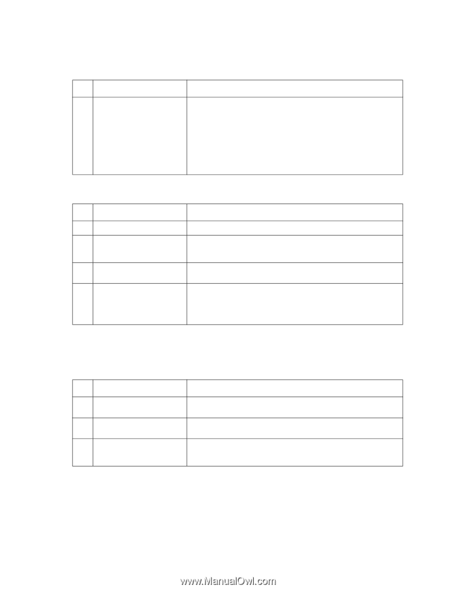
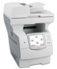
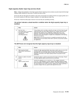
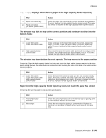
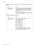
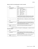
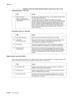
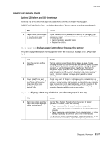
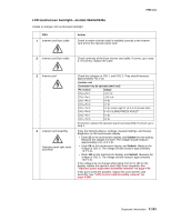
7002-xxx Tray x Paper Low displays when the high-capacity feeder input tray is full or has adequate paper in the tray FRU 1 Paper low switch Paper low switch cable High-capacity feeder option control board Action Run the sensor diagnostics for tray x (x=the number that represents the high-capacity input tray). If the test fails, check the voltage at J3-1 (gray). The voltage measures approximately +24 V dc. If incorrect, disconnect the paper low switch cable from J3 and measure the voltage again on J3-1. If incorrect, replace the high-capacity feeder option control board. If correct, check the cable for a short between pins 1 and 2 on the cable. If incorrect, replace the cable. If correct, check the switch for a bent or deformed actuator lever or defective switch. If incorrect, replace the switch. Excessive noise or vibration FRU 1 DC motor assembly 2 Idler pulley DC motor assembly 3 Drive pulley 4 Motor drive belt tray drive belt Action Make sure all the motor plate mounting screws are tight. Make sure the idler pulley is not binding on the pulley shaft. Check the pulley for wear. Check the idler pulley shaft on the motor mounting plate for damage or contamination. Check the drive pulley for wear, binds or damage to the pulley or pulley shaft. Make sure the pulley turns freely on the pulley shaft. Check the DC motor drive belt for damage. Make sure the belt is tracking correctly on the drive pulley, idler pulley, and motor pulley. Check the tray drive belt for damage. Make sure the belt is tracking correctly on the lower section of the drive pulley and lead screw pulleys. Input sensor service check Service tip: Run the Base Sensor Test. Check the input sensor for proper operation. The display changes from open to closed as the sensor flag is manually moved in and out of the sensor. FRU 1 Input sensor flag 2 System board 3 Input sensor cable Action Check the input sensor flag for damage and proper operation. If a problem is found, repair as necessary. Check for approximately +5 V dc at J15-10 on the system board. If incorrect, replace the system board. Check the continuity of the input sensor cable section of the front wiring harness. If incorrect, replace the harness. If correct, replace the input sensor assembly. 2-146 Service Manual
-
 1
1 -
2
-
3
-
4
-
5
-
6
-
7
-
8
-
9
-
10
-
11
-
12
-
13
-
14
-
15
-
16
-
17
-
18
-
19
-
20
-
21
-
22
-
23
-
24
-
25
-
26
-
27
-
28
-
29
-
30
-
31
-
32
-
33
-
34
-
35
-
36
-
37
-
38
-
39
-
40
-
41
-
42
-
43
-
44
-
45
-
46
-
47
-
48
-
49
-
50
-
51
-
52
-
53
-
54
-
55
-
56
-
57
-
58
-
59
-
60
-
61
-
62
-
63
-
64
-
65
-
66
-
67
-
68
-
69
-
70
-
71
-
72
-
73
-
74
-
75
-
76
-
77
-
78
-
79
-
80
-
81
-
82
-
83
-
84
-
85
-
86
-
87
-
88
-
89
-
90
-
91
-
92
-
93
-
94
-
95
-
96
-
97
-
98
-
99
-
100
-
101
-
102
-
103
-
104
-
105
-
106
-
107
-
108
-
109
-
110
-
111
-
112
-
113
-
114
-
115
-
116
-
117
-
118
-
119
-
120
-
121
-
122
-
123
-
124
-
125
-
126
-
127
-
128
-
129
-
130
-
131
-
132
-
133
-
134
-
135
-
136
-
137
-
138
-
139
-
140
-
141
-
142
-
143
-
144
-
145
-
146
-
147
-
148
-
149
-
150
-
151
-
152
-
153
-
154
-
155
-
156
-
157
-
158
-
159
-
160
-
161
-
162
-
163
-
164
-
165
-
166
-
167
-
168
-
169
-
170
-
171
-
172
-
173
-
174
-
175
-
176
-
177
-
178
-
 179
179 -
 180
180 -
 181
181 -
 182
182 -
 183
183 -
 184
184 -
 185
185 -
 186
186 -
 187
187 -
 188
188 -
 189
189 -
190
-
191
-
192
-
193
-
194
-
195
-
196
-
197
-
198
-
199
-
200
-
201
-
202
-
203
-
204
-
205
-
206
-
207
-
208
-
209
-
210
-
211
-
212
-
213
-
214
-
215
-
216
-
217
-
218
-
219
-
220
-
221
-
222
-
223
-
224
-
225
-
226
-
227
-
228
-
229
-
230
-
231
-
232
-
233
-
234
-
235
-
236
-
237
-
238
-
239
-
240
-
241
-
242
-
243
-
244
-
245
-
246
-
247
-
248
-
249
-
250
-
251
-
252
-
253
-
254
-
255
-
256
-
257
-
258
-
259
-
260
-
261
-
262
-
263
-
264
-
265
-
266
-
267
-
268
-
269
-
270
-
271
-
272
-
273
-
274
-
275
-
276
-
277
-
278
-
279
-
280
-
281
-
282
-
283
-
284
-
285
-
286
-
287
-
288
-
289
-
290
-
291
-
292
-
293
-
294
-
295
-
296
-
297
-
298
-
299
-
300
-
301
-
302
-
303
-
304
-
305
-
306
-
307
-
308
-
309
-
310
-
311
-
312
-
313
-
314
-
315
-
316
-
317
-
318
-
319
-
320
-
321
-
322
-
323
-
324
-
325
-
326
-
327
-
328
-
329
-
330
-
331
-
332
-
333
-
334
-
335
-
336
-
337
-
338
-
339
-
340
-
341
-
342
-
343
-
344
-
345
-
346
-
347
-
348
-
349
-
350
-
351
-
352
-
353
-
354
-
355
-
356
-
357
-
358
-
359
-
360
-
361
-
362
-
363
-
364
-
365
-
366
-
367
-
368
-
369
-
370
-
371
-
372
-
373
-
374
-
375
-
376
-
377
-
378
-
379
-
380
-
381
-
382
-
383
-
384
-
385
-
386
-
387
-
388
-
389
-
390
-
391
-
392
-
393
-
394
-
395
-
396
-
397
-
398
-
399
-
400
-
401
-
402
-
403
-
404
-
405
-
406
-
407
-
408
-
409
-
410
-
411
-
412
-
413
-
414
-
415
-
416
-
417
-
418
-
419
-
420
-
421
-
422
-
423
-
424
-
425
-
426
-
427
-
428
-
429
-
430
-
431
-
432
-
433
-
434
-
435
-
436
-
437
-
438
-
439
-
440
-
441
-
442
-
443
-
444
-
445
-
446
-
447
-
448
-
449
-
450
-
451
-
452
-
453
-
454
-
455
-
456
-
457
-
458
-
459
-
460
-
461
-
462
-
463
-
464
-
465
-
466
-
467
-
468
-
469
-
470
-
471
-
472
-
473
-
474
-
475
-
476
-
477
-
478
-
479
-
480
-
481
-
482
-
483
-
484
-
485
-
486
-
487
-
488
-
489
-
490
-
491
-
492
-
493
-
494
-
495
-
496
-
497
-
498
-
499
-
500
-
501
-
502
-
503
-
504
-
505
-
506
-
507
-
508
-
509
-
510
-
511
-
512
-
513
-
514
-
515
-
516
-
517
-
518
-
519
-
520
-
521
-
522
-
523
-
524
-
525
 |
 |