Lexmark X644E Service Manual - Page 173
xx-Hot fuser service check
 |
UPC - 734646093156
View all Lexmark X644E manuals
Add to My Manuals
Save this manual to your list of manuals |
Page 173 highlights
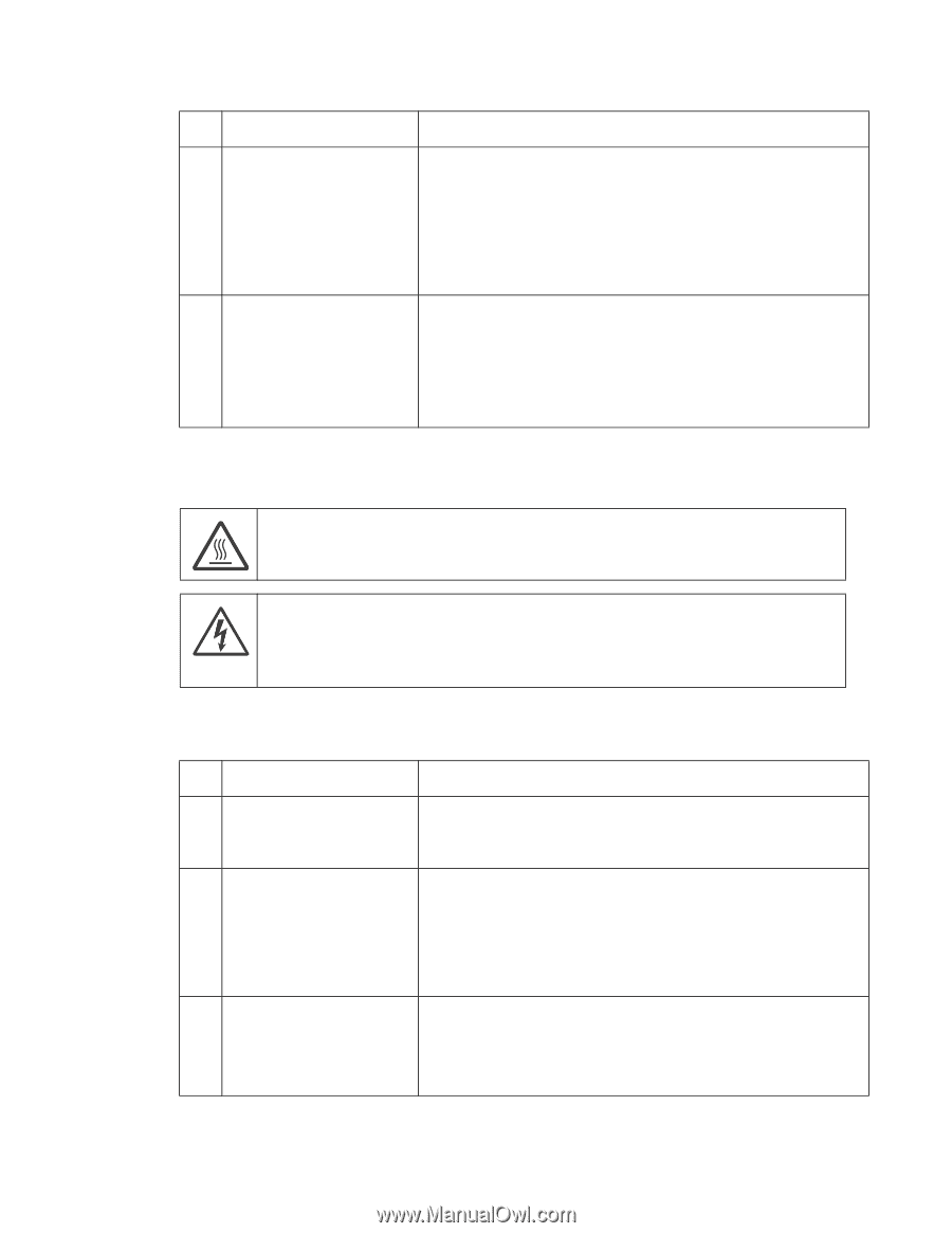
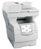
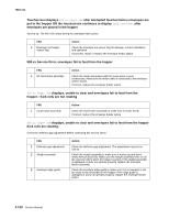
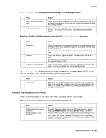
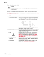
7002-xxx FRU 5 Fuser top cover assembly (thermistor, thermistor cable) Fuser to system board DC cable 6 Fuser assembly Action Check to make sure that the thermistor is installed correctly to J5 on the fuser control card. If installed correctly check the cable for any signs of damage. If any problems are found, replace the fuser top cover assembly."Fuser narrow media sensor removal" on page 4-88. If no problem is found, check the fuser to system board DC cable for correct installation at J1 on the fuser control card. If no problem is found, check the fuser to system board cable for correct installation at J10 on the system board. If no problem is found, go to step 6. If no problem is found up to this point, then replace the following in the order shown: • Fuser assembly. See "Fuser assembly removal" on page 4-79. • System board assembly. See "System board and inner shield removal -models X644e/X646e" on page 4-131. • LVPS. See "Low voltage power supply removal" on page 4-109. 923.xx-Hot fuser service check Error Code 923.xx, 924.xx, and 925.xx may display for a hot fuser failure. CAUTION The fuser may be hot, use caution before removing or servicing. CAUTION There is a danger from hazardous voltage in the area of the product where you are working. Unplug the product before you begin, or use caution if the product must receive power in order to perform the task. Service tip: Set the Fuser Temperature to NORMAL before starting this service check. In Diagnostics mode, In Diagnostics mode, select EP SETUP, and Fuser Temp. FRU 1 Fuser assembly 2 Fuser top cover assembly (thermistor) 3 System board Fuser top cover assembly Action Check for any signs of overheating in the fuser assembly. Check the hot roll, hot roll bearings, and the area around the thermistor for any signs of excessive heat. If a problem is found, replace the thermistor. If no problem is found, go to step 2. Turn the printer off and disconnect the fuser to system board cable from J10 on the system board. Check the resistance between pins J10-3 and J10-4. The resistance should be greater than 100K ohms. If correct, go to step 3; if incorrect, disconnect the thermistor cable from J5 on the fuser board and measure the resistance between the two pins on the thermistor cable. If incorrect, replace the fuser top cover assembly (see "Fuser narrow media sensor removal" on page 4-88); if correct, replace the fuser to system board cable. Check the voltage on J10-3 ground on the system board. The voltage should measure approximately +3.3 V dc. If the voltage is correct, replace the fuser top cover assembly. See "Fuser narrow media sensor removal" on page 4-88. If incorrect, replace the system board. See "System board and inner shield removal -models X644e/X646e" on page 4-131. Diagnostic information 2-135
-
 1
1 -
2
-
3
-
4
-
5
-
6
-
7
-
8
-
9
-
10
-
11
-
12
-
13
-
14
-
15
-
16
-
17
-
18
-
19
-
20
-
21
-
22
-
23
-
24
-
25
-
26
-
27
-
28
-
29
-
30
-
31
-
32
-
33
-
34
-
35
-
36
-
37
-
38
-
39
-
40
-
41
-
42
-
43
-
44
-
45
-
46
-
47
-
48
-
49
-
50
-
51
-
52
-
53
-
54
-
55
-
56
-
57
-
58
-
59
-
60
-
61
-
62
-
63
-
64
-
65
-
66
-
67
-
68
-
69
-
70
-
71
-
72
-
73
-
74
-
75
-
76
-
77
-
78
-
79
-
80
-
81
-
82
-
83
-
84
-
85
-
86
-
87
-
88
-
89
-
90
-
91
-
92
-
93
-
94
-
95
-
96
-
97
-
98
-
99
-
100
-
101
-
102
-
103
-
104
-
105
-
106
-
107
-
108
-
109
-
110
-
111
-
112
-
113
-
114
-
115
-
116
-
117
-
118
-
119
-
120
-
121
-
122
-
123
-
124
-
125
-
126
-
127
-
128
-
129
-
130
-
131
-
132
-
133
-
134
-
135
-
136
-
137
-
138
-
139
-
140
-
141
-
142
-
143
-
144
-
145
-
146
-
147
-
148
-
149
-
150
-
151
-
152
-
153
-
154
-
155
-
156
-
157
-
158
-
159
-
160
-
161
-
162
-
163
-
164
-
165
-
166
-
167
-
 168
168 -
 169
169 -
 170
170 -
 171
171 -
 172
172 -
 173
173 -
 174
174 -
 175
175 -
 176
176 -
 177
177 -
 178
178 -
179
-
180
-
181
-
182
-
183
-
184
-
185
-
186
-
187
-
188
-
189
-
190
-
191
-
192
-
193
-
194
-
195
-
196
-
197
-
198
-
199
-
200
-
201
-
202
-
203
-
204
-
205
-
206
-
207
-
208
-
209
-
210
-
211
-
212
-
213
-
214
-
215
-
216
-
217
-
218
-
219
-
220
-
221
-
222
-
223
-
224
-
225
-
226
-
227
-
228
-
229
-
230
-
231
-
232
-
233
-
234
-
235
-
236
-
237
-
238
-
239
-
240
-
241
-
242
-
243
-
244
-
245
-
246
-
247
-
248
-
249
-
250
-
251
-
252
-
253
-
254
-
255
-
256
-
257
-
258
-
259
-
260
-
261
-
262
-
263
-
264
-
265
-
266
-
267
-
268
-
269
-
270
-
271
-
272
-
273
-
274
-
275
-
276
-
277
-
278
-
279
-
280
-
281
-
282
-
283
-
284
-
285
-
286
-
287
-
288
-
289
-
290
-
291
-
292
-
293
-
294
-
295
-
296
-
297
-
298
-
299
-
300
-
301
-
302
-
303
-
304
-
305
-
306
-
307
-
308
-
309
-
310
-
311
-
312
-
313
-
314
-
315
-
316
-
317
-
318
-
319
-
320
-
321
-
322
-
323
-
324
-
325
-
326
-
327
-
328
-
329
-
330
-
331
-
332
-
333
-
334
-
335
-
336
-
337
-
338
-
339
-
340
-
341
-
342
-
343
-
344
-
345
-
346
-
347
-
348
-
349
-
350
-
351
-
352
-
353
-
354
-
355
-
356
-
357
-
358
-
359
-
360
-
361
-
362
-
363
-
364
-
365
-
366
-
367
-
368
-
369
-
370
-
371
-
372
-
373
-
374
-
375
-
376
-
377
-
378
-
379
-
380
-
381
-
382
-
383
-
384
-
385
-
386
-
387
-
388
-
389
-
390
-
391
-
392
-
393
-
394
-
395
-
396
-
397
-
398
-
399
-
400
-
401
-
402
-
403
-
404
-
405
-
406
-
407
-
408
-
409
-
410
-
411
-
412
-
413
-
414
-
415
-
416
-
417
-
418
-
419
-
420
-
421
-
422
-
423
-
424
-
425
-
426
-
427
-
428
-
429
-
430
-
431
-
432
-
433
-
434
-
435
-
436
-
437
-
438
-
439
-
440
-
441
-
442
-
443
-
444
-
445
-
446
-
447
-
448
-
449
-
450
-
451
-
452
-
453
-
454
-
455
-
456
-
457
-
458
-
459
-
460
-
461
-
462
-
463
-
464
-
465
-
466
-
467
-
468
-
469
-
470
-
471
-
472
-
473
-
474
-
475
-
476
-
477
-
478
-
479
-
480
-
481
-
482
-
483
-
484
-
485
-
486
-
487
-
488
-
489
-
490
-
491
-
492
-
493
-
494
-
495
-
496
-
497
-
498
-
499
-
500
-
501
-
502
-
503
-
504
-
505
-
506
-
507
-
508
-
509
-
510
-
511
-
512
-
513
-
514
-
515
-
516
-
517
-
518
-
519
-
520
-
521
-
522
-
523
-
524
-
525
 |
 |