Yamaha 01V96i Reference Manual - Page 17
Input Channels
 |
View all Yamaha 01V96i manuals
Add to My Manuals
Save this manual to your list of manuals |
Page 17 highlights
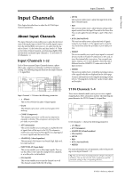
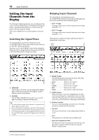
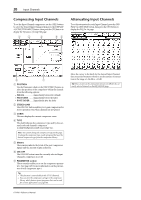
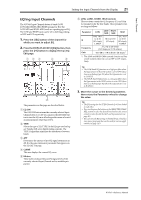
Input Channels Input Channels 17 Input Channels This chapter describes how to adjust the 01V96i's Input Channel parameters. About Input Channels The input Channel section enables you to adjust the level and tone of the signals input to the 01V96i (and the signals output from the internal Effects processors 1-4), and route the signals to Buses 1-8, the Stereo Bus, and Aux Sends 1-8. There are two types of Input Channels, each featuring slightly different functions: monaural Input Channels 1-32 and stereo ST IN Channels 1-4. Input Channels 1-32 Each of these monaural Input Channels features a phase effect, gate, compressor, attenuator, and EQ for signal processing. The following diagram illustrates the Input Channel 1-32 signal flow. • LEVEL This section enables you to adjust the input level of the Input Channel signal. • PAN This section enables you to adjust the pan setting of the signals routed from the Input Channels to the Stereo Bus. You can also apply the pan setting to a pair of Bus channels. • AUX (Aux Send level) This section enables you to adjust the level of signals routed to Aux Sends 1-8. The signals can be routed to Aux Sends from either the pre-fader or post-fader position. • INSERT This section enables you to patch input signals to external devices via the on-board I/O connectors or I/O card, or insert the internal effect processors. You can patch any inputs, outputs, or I/O card channels. (Note that this is different from the INSERT I/O connectors in the AD Input section.) • METER This section enables you to switch the metering position of the signal levels that are displayed in the Meter page. For more information on selecting the metering position, refer to "Viewing the Level Meters" in the Owner's Manual (booklet). INPUT PATCH INPUT PATCH Input Channels 1-32 feature the following parameters: • (Phase) This section switches the phase of input signals. • GATE This dynamics processor can be used as a gate or for ducking. • COMP (Compressor) This dynamics processor can be used as compressor, expander or limiter. The compressor can be pre-EQ, pre-fader, or post-fader. • ATT (Attenuator) This section enables you to attenuate or amplify the level of signals that will be input to the EQ. The attenuator enables you to prevent post-EQ signals from clipping and to correct signal levels that are too low. • 4 BAND EQ (4-band equalizer) This parametric EQ features four bands (high, high-mid, low-mid, and low). • INPUT DELAY (Input delay) This section enables you to delay input signals. You can use this delay to fine-tune the timing between channels, or as a delay effect with feedback. • ON (On/Off) This section enables you to turn the channel on or off. The channel is muted with the Off setting. ST IN Channels 1-4 These stereo channels enable you to process stereo signals using the phase effect, attenuator, and EQ. The following diagram illustrates the ST IN Channel 1-4 signal flow. ST IN Channels 1-4 feature the following parameters: • (Phase) • ATT (Attenuator) • 4 BAND EQ (4-band equalizer) • ON (On/Off) • LEVEL • PAN • AUX (Aux Send level) • METER For more information on each parameter, refer to the preceding section Input Channel 1-32. Tip: You can store these channel parameter settings in the Channel library. You can also store the Gate, Compressor, and EQ parameter settings to the corresponding libraries. 01V96i-Reference Manual
-
 1
1 -
2
-
3
-
4
-
5
-
6
-
7
-
8
-
9
-
10
-
11
-
 12
12 -
 13
13 -
 14
14 -
 15
15 -
 16
16 -
 17
17 -
 18
18 -
 19
19 -
 20
20 -
 21
21 -
 22
22 -
23
-
24
-
25
-
26
-
27
-
28
-
29
-
30
-
31
-
32
-
33
-
34
-
35
-
36
-
37
-
38
-
39
-
40
-
41
-
42
-
43
-
44
-
45
-
46
-
47
-
48
-
49
-
50
-
51
-
52
-
53
-
54
-
55
-
56
-
57
-
58
-
59
-
60
-
61
-
62
-
63
-
64
-
65
-
66
-
67
-
68
-
69
-
70
-
71
-
72
-
73
-
74
-
75
-
76
-
77
-
78
-
79
-
80
-
81
-
82
-
83
-
84
-
85
-
86
-
87
-
88
-
89
-
90
-
91
-
92
-
93
-
94
-
95
-
96
-
97
-
98
-
99
-
100
-
101
-
102
-
103
-
104
-
105
-
106
-
107
-
108
-
109
-
110
-
111
-
112
-
113
-
114
-
115
-
116
-
117
-
118
-
119
-
120
-
121
-
122
-
123
-
124
-
125
-
126
-
127
-
128
-
129
-
130
-
131
-
132
-
133
-
134
-
135
-
136
-
137
-
138
-
139
-
140
-
141
-
142
-
143
-
144
-
145
-
146
-
147
-
148
-
149
-
150
-
151
-
152
-
153
-
154
-
155
-
156
-
157
-
158
-
159
-
160
-
161
-
162
-
163
-
164
-
165
-
166
-
167
-
168
-
169
-
170
-
171
-
172
-
173
-
174
-
175
-
176
-
177
-
178
-
179
-
180
-
181
-
182
-
183
-
184
-
185
-
186
 |
 |
