Yamaha 01V96i Reference Manual - Page 23
Viewing Input Channel Settings, Viewing the Gate, Compressor, and, EQ Settings
 |
View all Yamaha 01V96i manuals
Add to My Manuals
Save this manual to your list of manuals |
Page 23 highlights
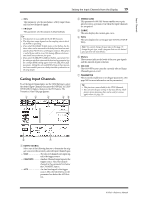
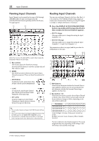
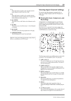
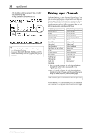
Input Channels Setting the Input Channels from the Display 23 3S When this button is turned on, the currently-selected Input Channel is routed to the Stereo Bus. 4D When this button is turned on, the currently-selected Input Channel is routed to its Direct Out. See page 46 for more information on the Direct Out. 5 ALL STEREO This button turns on the S button for all channels on the page. 6 ALL BUS This button turns on the Bus buttons 1-8 for all channels on the page. 7 ALL CLEAR This button clears all routing assignments on the page. 8 SURROUND MODE This field displays the current Surround mode. Tip: The routings of the ST IN Channels L/R are linked. The D button is unavailable for the ST IN Channels. Viewing Input Channel Settings You can view and adjust parameter settings for the currently-selected Input Channel on the View | Parameter or Fader pages. ■ Viewing the Gate, Compressor, and EQ Settings To display the View | Parameter page for a specific Input Channel, use the corresponding [SEL] button to select the desired channel, then press the DISPLAY ACCESS [VIEW] button repeatedly. Move the cursor to a parameter you wish to change, then rotate the Parameter wheel or press the [INC]/[DEC] buttons or [ENTER] button to modify the setting. 43 65 1 2 78 The following parameters are available (sections marked with an asterisk (*) are unavailable for the ST IN Channels). 1 GATE section (*) This section enables you to turn the gate-type dynamics processor on or off and set the parameters. (See page 19 for more information.) 2 COMP section (*) This section enables you to turn the compressor-type dynamics processor on or off and set the parameters. (See page 20 for more information.) 3 INSERT section (*) This section enables you to turn the Insert on or off and patch the Insert In and Out. (See page 47 for more information.) 4 EQ section This section enables you to set various EQ parameters. (See page 21 for more information.) 5 Meters These meters indicate the signal levels of the currently-selected Input Channel and its available pair partner. 6 (Phase) section You can reverse the signal phase of the currently-selected Input Channel. (See page 18 for more information.) 01V96i-Reference Manual
-
 1
1 -
2
-
3
-
4
-
5
-
6
-
7
-
8
-
9
-
10
-
11
-
12
-
13
-
14
-
15
-
16
-
17
-
 18
18 -
 19
19 -
 20
20 -
 21
21 -
 22
22 -
 23
23 -
 24
24 -
 25
25 -
 26
26 -
 27
27 -
 28
28 -
29
-
30
-
31
-
32
-
33
-
34
-
35
-
36
-
37
-
38
-
39
-
40
-
41
-
42
-
43
-
44
-
45
-
46
-
47
-
48
-
49
-
50
-
51
-
52
-
53
-
54
-
55
-
56
-
57
-
58
-
59
-
60
-
61
-
62
-
63
-
64
-
65
-
66
-
67
-
68
-
69
-
70
-
71
-
72
-
73
-
74
-
75
-
76
-
77
-
78
-
79
-
80
-
81
-
82
-
83
-
84
-
85
-
86
-
87
-
88
-
89
-
90
-
91
-
92
-
93
-
94
-
95
-
96
-
97
-
98
-
99
-
100
-
101
-
102
-
103
-
104
-
105
-
106
-
107
-
108
-
109
-
110
-
111
-
112
-
113
-
114
-
115
-
116
-
117
-
118
-
119
-
120
-
121
-
122
-
123
-
124
-
125
-
126
-
127
-
128
-
129
-
130
-
131
-
132
-
133
-
134
-
135
-
136
-
137
-
138
-
139
-
140
-
141
-
142
-
143
-
144
-
145
-
146
-
147
-
148
-
149
-
150
-
151
-
152
-
153
-
154
-
155
-
156
-
157
-
158
-
159
-
160
-
161
-
162
-
163
-
164
-
165
-
166
-
167
-
168
-
169
-
170
-
171
-
172
-
173
-
174
-
175
-
176
-
177
-
178
-
179
-
180
-
181
-
182
-
183
-
184
-
185
-
186
 |
 |
