D-Link DGS-3324SR Product Manual - Page 131
Priority, Class, Flowlabel, Source IPv6 Address, Destination IPv6, Address, Auto Assign, Access ID
 |
UPC - 790069262067
View all D-Link DGS-3324SR manuals
Add to My Manuals
Save this manual to your list of manuals |
Page 131 highlights
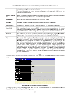
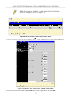
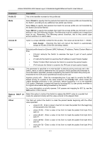
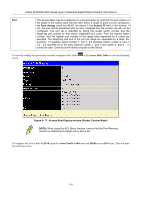
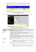
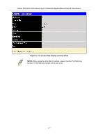
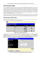
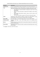
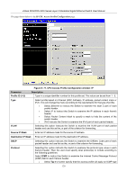
xStack DGS/DXS-3300 Series Layer 3 Stackable Gigabit Ethernet Switch User Manual • Packet Content Mask instructs the Switch to examine the packet header. • IPv6 instructs the Switch to examine the IPv6 part of each packet header. Priority This parameter is specified to re-write the 802.1p default priority previously set in the Switch, which is used to determine the CoS queue to which packets are forwarded to. Once this field is specified, packets accepted by the Switch that match this priority are forwarded to the CoS queue specified previously by the user. Replace priority with − Click the corresponding box to re-write the 802.1p default priority of a packet to the value entered in the Priority field, which meets the criteria specified previously in this command, before forwarding it on to the specified CoS queue. Otherwise, a packet will have its incoming 802.1p user priority re-written to its original value before being forwarded by the Switch. For more information on priority queues, CoS queues and mapping for 802.1p, see the QoS section of this manual. Class Entering a value between 0 and 255 will instruct the Switch to examine the class field of the IPv6 header. This class field is a part of the packet header that is similar to the Type of Service (ToS) or Precedence bits field of IPv4. Flowlabel Configuring this field, in hex form, will instruct the Switch to examine the flow label field of the IPv6 header. This flow label field is used by a source to label sequences of packets such as non-default quality of service or real time service packets. Source IPv6 Address The user may specify an IP address mask for the source IPv6 address by entering the IP address mask, in hex form. Destination IPv6 Address The user may specify an IP address mask for the destination IPv6 address by and entering the IP address mask, in hex form. Port The Access Rule may be configured on a per-port basis by entering the port number of the switch in the switch stack into this field. When a range of ports is to be configured, the Auto Assign check box MUST be clicked in the Access ID field of this window. If not, the user will be presented with an error message and the access rule will not be configured. The port list is specified by listing the lowest switch number and the beginning port number on that switch, separated by a colon. Then the highest switch number, and the highest port number of the range (also separated by a colon) are specified. The beginning and end of the port list range are separated by a dash. For example, 1:3 specifies switch number 1, port 3. 2:4 specifies switch number 2, port 4. 1:3 - 2:4 specifies all of the ports between switch 1, port 3 and switch 2, port 4 − in numerical order. Entering all will denote all ports on the Switch. To view the settings of a previously correctly configured rule, click screen: in the Access Rule Table to view the following 116
-
 1
1 -
2
-
3
-
4
-
5
-
6
-
7
-
8
-
9
-
10
-
11
-
12
-
13
-
14
-
15
-
16
-
17
-
18
-
19
-
20
-
21
-
22
-
23
-
24
-
25
-
26
-
27
-
28
-
29
-
30
-
31
-
32
-
33
-
34
-
35
-
36
-
37
-
38
-
39
-
40
-
41
-
42
-
43
-
44
-
45
-
46
-
47
-
48
-
49
-
50
-
51
-
52
-
53
-
54
-
55
-
56
-
57
-
58
-
59
-
60
-
61
-
62
-
63
-
64
-
65
-
66
-
67
-
68
-
69
-
70
-
71
-
72
-
73
-
74
-
75
-
76
-
77
-
78
-
79
-
80
-
81
-
82
-
83
-
84
-
85
-
86
-
87
-
88
-
89
-
90
-
91
-
92
-
93
-
94
-
95
-
96
-
97
-
98
-
99
-
100
-
101
-
102
-
103
-
104
-
105
-
106
-
107
-
108
-
109
-
110
-
111
-
112
-
113
-
114
-
115
-
116
-
117
-
118
-
119
-
120
-
121
-
122
-
123
-
124
-
125
-
 126
126 -
 127
127 -
 128
128 -
 129
129 -
 130
130 -
 131
131 -
 132
132 -
 133
133 -
 134
134 -
 135
135 -
 136
136 -
137
-
138
-
139
-
140
-
141
-
142
-
143
-
144
-
145
-
146
-
147
-
148
-
149
-
150
-
151
-
152
-
153
-
154
-
155
-
156
-
157
-
158
-
159
-
160
-
161
-
162
-
163
-
164
-
165
-
166
-
167
-
168
-
169
-
170
-
171
-
172
-
173
-
174
-
175
-
176
-
177
-
178
-
179
-
180
-
181
-
182
-
183
-
184
-
185
-
186
-
187
-
188
-
189
-
190
-
191
-
192
-
193
-
194
-
195
-
196
-
197
-
198
-
199
-
200
-
201
-
202
-
203
-
204
-
205
-
206
-
207
-
208
-
209
-
210
-
211
-
212
-
213
-
214
-
215
-
216
-
217
-
218
-
219
-
220
-
221
-
222
-
223
-
224
-
225
-
226
-
227
-
228
-
229
-
230
-
231
-
232
-
233
-
234
-
235
-
236
-
237
-
238
-
239
-
240
-
241
-
242
-
243
-
244
-
245
-
246
-
247
-
248
-
249
-
250
-
251
-
252
-
253
-
254
-
255
-
256
-
257
-
258
-
259
-
260
-
261
-
262
-
263
-
264
-
265
-
266
-
267
-
268
-
269
-
270
-
271
-
272
-
273
-
274
-
275
-
276
-
277
-
278
-
279
-
280
-
281
-
282
-
283
-
284
-
285
-
286
-
287
-
288
-
289
-
290
-
291
-
292
-
293
-
294
-
295
-
296
-
297
-
298
-
299
-
300
-
301
-
302
-
303
-
304
-
305
-
306
-
307
-
308
-
309
-
310
-
311
-
312
-
313
-
314
-
315
-
316
-
317
-
318
-
319
-
320
-
321
-
322
-
323
-
324
-
325
-
326
-
327
-
328
-
329
-
330
-
331
-
332
-
333
-
334
-
335
-
336
-
337
-
338
-
339
-
340
-
341
-
342
-
343
-
344
-
345
-
346
-
347
-
348
-
349
-
350
-
351
-
352
-
353
-
354
-
355
-
356
-
357
-
358
-
359
-
360
-
361
-
362
-
363
-
364
-
365
-
366
-
367
-
368
-
369
-
370
-
371
-
372
-
373
-
374
-
375
-
376
-
377
-
378
-
379
-
380
-
381
-
382
-
383
-
384
-
385
-
386
-
387
-
388
-
389
-
390
-
391
-
392
 |
 |