D-Link DGS-3324SR Product Manual - Page 162
IP Multinetting, IP Interface Setup
 |
UPC - 790069262067
View all D-Link DGS-3324SR manuals
Add to My Manuals
Save this manual to your list of manuals |
Page 162 highlights
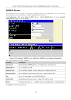
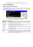
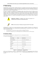
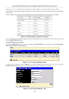
xStack DGS/DXS-3300 Series Layer 3 Stackable Gigabit Ethernet Switch User Manual IP Multinetting IP Multinetting is a function that allows multiple IP interfaces to be assigned to the same VLAN. This is beneficial to the administrator when the number of IPs on the original interface is insufficient and the network administrator wishes not to resize the interface. IP Multinetting is capable of assigning another IP interface on the same VLAN without affecting the original stations or settings of the original interface. Two types of interfaces are configured for IP multinetting, primary and secondary, and every IP interface must be classified as one of these. A primary interface refers to the first interface created on a VLAN, with no exceptions. All other interfaces created will be regarded as secondary only, and can only be created once a primary interface has been configured. There may be five interfaces per VLAN (one primary, and up to four secondary) and they are, in most cases, independent of each other. Primary interfaces cannot be deleted if the VLAN contains a secondary interface. Once the user creates multiple interfaces for a specified VLAN (primary and secondary), that set IP interface cannot be changed to another VLAN. Application Limitation: A multicast router cannot be connected to IP interfaces that are utilizing the IP Multinetting function. NOTE: Only the primary IP interface will support the BOOTP relay agent. IP Multinetting is a valuable tool for network administrators requiring a multitude of IP addresses, but configuring the Switch for IP multinetting may cause troubleshooting and bandwidth problems, and should not be used as a long term solution. Problems may include: • The Switch may use extra resources to process packets for multiple IP interfaces. • The amount of broadcast data, such as RIP update packets and PIM hello packets, will be increased. IP Interface Setup Each VLAN must be configured prior to setting up the VLAN's corresponding IP interface. An example is presented below: VLAN Name VID Switch Ports System (default) 1 5, 6, 7, 8, 21, 22, 23, 24 Engineer 2 9, 10, 11, 12 Marketing 3 13, 14, 15, 16 Finance 4 17, 18, 19, 20 Sales 5 1, 2, 3, 4 Backbone 6 25, 26 Table 6- 4. VLAN Example - Assigned Ports In this case, six IP interfaces are required, so a CIDR notation of 10.32.0.0/11 (or a 11-bit) addressing scheme will work. This addressing scheme will give a subnet mask of 11111111.11100000.00000000.00000000 (binary) or 255.224.0.0 (decimal). 147
-
 1
1 -
2
-
3
-
4
-
5
-
6
-
7
-
8
-
9
-
10
-
11
-
12
-
13
-
14
-
15
-
16
-
17
-
18
-
19
-
20
-
21
-
22
-
23
-
24
-
25
-
26
-
27
-
28
-
29
-
30
-
31
-
32
-
33
-
34
-
35
-
36
-
37
-
38
-
39
-
40
-
41
-
42
-
43
-
44
-
45
-
46
-
47
-
48
-
49
-
50
-
51
-
52
-
53
-
54
-
55
-
56
-
57
-
58
-
59
-
60
-
61
-
62
-
63
-
64
-
65
-
66
-
67
-
68
-
69
-
70
-
71
-
72
-
73
-
74
-
75
-
76
-
77
-
78
-
79
-
80
-
81
-
82
-
83
-
84
-
85
-
86
-
87
-
88
-
89
-
90
-
91
-
92
-
93
-
94
-
95
-
96
-
97
-
98
-
99
-
100
-
101
-
102
-
103
-
104
-
105
-
106
-
107
-
108
-
109
-
110
-
111
-
112
-
113
-
114
-
115
-
116
-
117
-
118
-
119
-
120
-
121
-
122
-
123
-
124
-
125
-
126
-
127
-
128
-
129
-
130
-
131
-
132
-
133
-
134
-
135
-
136
-
137
-
138
-
139
-
140
-
141
-
142
-
143
-
144
-
145
-
146
-
147
-
148
-
149
-
150
-
151
-
152
-
153
-
154
-
155
-
156
-
 157
157 -
 158
158 -
 159
159 -
 160
160 -
 161
161 -
 162
162 -
 163
163 -
 164
164 -
 165
165 -
 166
166 -
 167
167 -
168
-
169
-
170
-
171
-
172
-
173
-
174
-
175
-
176
-
177
-
178
-
179
-
180
-
181
-
182
-
183
-
184
-
185
-
186
-
187
-
188
-
189
-
190
-
191
-
192
-
193
-
194
-
195
-
196
-
197
-
198
-
199
-
200
-
201
-
202
-
203
-
204
-
205
-
206
-
207
-
208
-
209
-
210
-
211
-
212
-
213
-
214
-
215
-
216
-
217
-
218
-
219
-
220
-
221
-
222
-
223
-
224
-
225
-
226
-
227
-
228
-
229
-
230
-
231
-
232
-
233
-
234
-
235
-
236
-
237
-
238
-
239
-
240
-
241
-
242
-
243
-
244
-
245
-
246
-
247
-
248
-
249
-
250
-
251
-
252
-
253
-
254
-
255
-
256
-
257
-
258
-
259
-
260
-
261
-
262
-
263
-
264
-
265
-
266
-
267
-
268
-
269
-
270
-
271
-
272
-
273
-
274
-
275
-
276
-
277
-
278
-
279
-
280
-
281
-
282
-
283
-
284
-
285
-
286
-
287
-
288
-
289
-
290
-
291
-
292
-
293
-
294
-
295
-
296
-
297
-
298
-
299
-
300
-
301
-
302
-
303
-
304
-
305
-
306
-
307
-
308
-
309
-
310
-
311
-
312
-
313
-
314
-
315
-
316
-
317
-
318
-
319
-
320
-
321
-
322
-
323
-
324
-
325
-
326
-
327
-
328
-
329
-
330
-
331
-
332
-
333
-
334
-
335
-
336
-
337
-
338
-
339
-
340
-
341
-
342
-
343
-
344
-
345
-
346
-
347
-
348
-
349
-
350
-
351
-
352
-
353
-
354
-
355
-
356
-
357
-
358
-
359
-
360
-
361
-
362
-
363
-
364
-
365
-
366
-
367
-
368
-
369
-
370
-
371
-
372
-
373
-
374
-
375
-
376
-
377
-
378
-
379
-
380
-
381
-
382
-
383
-
384
-
385
-
386
-
387
-
388
-
389
-
390
-
391
-
392
 |
 |