D-Link DGS-3324SR Product Manual - Page 223
PIM Parameter Settings
 |
UPC - 790069262067
View all D-Link DGS-3324SR manuals
Add to My Manuals
Save this manual to your list of manuals |
Page 223 highlights
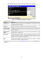
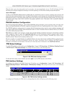
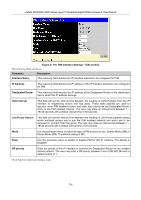
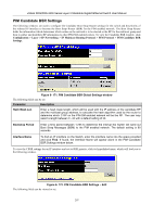
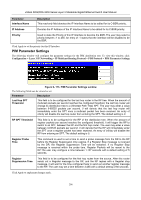
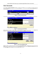
xStack DGS/DXS-3300 Series Layer 3 Stackable Gigabit Ethernet Switch User Manual Parameter Interface Name Description This read-only field denotes the IP Interface Name to be edited for its C-BSR priority. IP Address Denotes the IP Address of the IP Interface Name to be edited for its C-BSR priority. Priority Used to state the Priority of this IP Interface to become the BSR. The user may select a priority between -1 to 255. An entry of -1 states that the interface will be disabled to be the BSR. Click Apply to set the priority for this IP Interface. PIM Parameter Settings The following window will configure the parameter settings for the PIM distribution tree. To view this window, click Configuration > Layer 3 IP Networking > IP Multicast Routing Protocol > PIM Protocol > PIM Parameter Settings. Figure 6- 173. PIM Parameter Settings window The following fields can be viewed or set: Parameter Description Last Hop SPT Threshold This field is to be configured for the last hop router in the RP tree. When the amount of multicast packets per second reaches the configured threshold, the last hop router will change its distribution tree to a (Shortest Path Tree) SPT. The user may enter a value between 0-65535 packets per second. 0 will denote that the last hop router will immediately enter the SPT once a multicast packet has been received. An entry of infinity will disable the last hop router from entering the SPT. The default setting is 0. RP SPT Threshold This field is to be configured for the RP of the distribution tree. When the amount of register packets per second reaches the configured threshold, it will trigger the RP to switch to an SPT, between the RP and the first hop router. The user may enter a value between 0-65535 packets per second. 0 will denote that the RP will immediately enter the SPT once a register packet has been received. An entry of infinity will disable the RP from entering an SPT. The default setting is 0. Register Probe Time This command is used to set a time to send a probe message from the DR to the RP before the Register Suppression time expires. If a Register Stop message is received by the DR, the Register Suppression Time will be restarted. If no Register Stop message is received within the probe time, Register Packets will be resent to the RP.The user may configure a time between 1-127 seconds with a default setting of 5 seconds. Register Suppression Time This field is to be configured for the first hop router from the source. After this router sends out a Register message to the RP, and the RP replies with a Register stop message, it will wait for the time configured here to send out another register message to the RP. The user may set a time between 3-255 with a default setting of 60 seconds. Click Apply to implement changes made. 208
-
 1
1 -
2
-
3
-
4
-
5
-
6
-
7
-
8
-
9
-
10
-
11
-
12
-
13
-
14
-
15
-
16
-
17
-
18
-
19
-
20
-
21
-
22
-
23
-
24
-
25
-
26
-
27
-
28
-
29
-
30
-
31
-
32
-
33
-
34
-
35
-
36
-
37
-
38
-
39
-
40
-
41
-
42
-
43
-
44
-
45
-
46
-
47
-
48
-
49
-
50
-
51
-
52
-
53
-
54
-
55
-
56
-
57
-
58
-
59
-
60
-
61
-
62
-
63
-
64
-
65
-
66
-
67
-
68
-
69
-
70
-
71
-
72
-
73
-
74
-
75
-
76
-
77
-
78
-
79
-
80
-
81
-
82
-
83
-
84
-
85
-
86
-
87
-
88
-
89
-
90
-
91
-
92
-
93
-
94
-
95
-
96
-
97
-
98
-
99
-
100
-
101
-
102
-
103
-
104
-
105
-
106
-
107
-
108
-
109
-
110
-
111
-
112
-
113
-
114
-
115
-
116
-
117
-
118
-
119
-
120
-
121
-
122
-
123
-
124
-
125
-
126
-
127
-
128
-
129
-
130
-
131
-
132
-
133
-
134
-
135
-
136
-
137
-
138
-
139
-
140
-
141
-
142
-
143
-
144
-
145
-
146
-
147
-
148
-
149
-
150
-
151
-
152
-
153
-
154
-
155
-
156
-
157
-
158
-
159
-
160
-
161
-
162
-
163
-
164
-
165
-
166
-
167
-
168
-
169
-
170
-
171
-
172
-
173
-
174
-
175
-
176
-
177
-
178
-
179
-
180
-
181
-
182
-
183
-
184
-
185
-
186
-
187
-
188
-
189
-
190
-
191
-
192
-
193
-
194
-
195
-
196
-
197
-
198
-
199
-
200
-
201
-
202
-
203
-
204
-
205
-
206
-
207
-
208
-
209
-
210
-
211
-
212
-
213
-
214
-
215
-
216
-
217
-
 218
218 -
 219
219 -
 220
220 -
 221
221 -
 222
222 -
 223
223 -
 224
224 -
 225
225 -
 226
226 -
 227
227 -
 228
228 -
229
-
230
-
231
-
232
-
233
-
234
-
235
-
236
-
237
-
238
-
239
-
240
-
241
-
242
-
243
-
244
-
245
-
246
-
247
-
248
-
249
-
250
-
251
-
252
-
253
-
254
-
255
-
256
-
257
-
258
-
259
-
260
-
261
-
262
-
263
-
264
-
265
-
266
-
267
-
268
-
269
-
270
-
271
-
272
-
273
-
274
-
275
-
276
-
277
-
278
-
279
-
280
-
281
-
282
-
283
-
284
-
285
-
286
-
287
-
288
-
289
-
290
-
291
-
292
-
293
-
294
-
295
-
296
-
297
-
298
-
299
-
300
-
301
-
302
-
303
-
304
-
305
-
306
-
307
-
308
-
309
-
310
-
311
-
312
-
313
-
314
-
315
-
316
-
317
-
318
-
319
-
320
-
321
-
322
-
323
-
324
-
325
-
326
-
327
-
328
-
329
-
330
-
331
-
332
-
333
-
334
-
335
-
336
-
337
-
338
-
339
-
340
-
341
-
342
-
343
-
344
-
345
-
346
-
347
-
348
-
349
-
350
-
351
-
352
-
353
-
354
-
355
-
356
-
357
-
358
-
359
-
360
-
361
-
362
-
363
-
364
-
365
-
366
-
367
-
368
-
369
-
370
-
371
-
372
-
373
-
374
-
375
-
376
-
377
-
378
-
379
-
380
-
381
-
382
-
383
-
384
-
385
-
386
-
387
-
388
-
389
-
390
-
391
-
392
 |
 |