D-Link DGS-3324SR Product Manual - Page 21
LED Indicators, LED Indicators, Description, Power, Master, Console, Port LEDs - 3324sri manual
 |
UPC - 790069262067
View all D-Link DGS-3324SR manuals
Add to My Manuals
Save this manual to your list of manuals |
Page 21 highlights
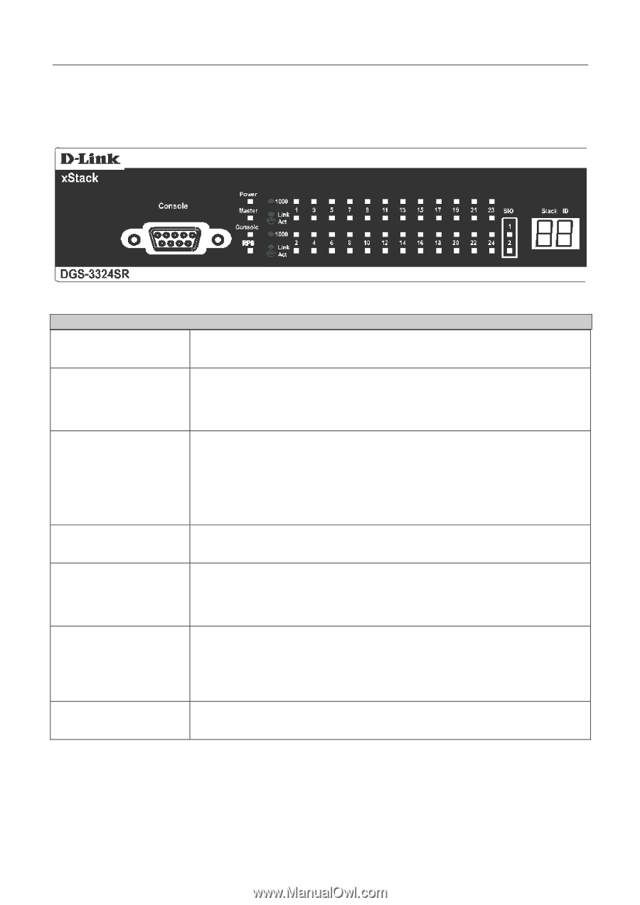
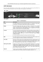
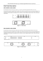
xStack DGS/DXS-3300 Series Layer 3 Stackable Gigabit Ethernet Switch User Manual LED Indicators The Switch supports LED indicators for Power, Master, Console, RPS, SIO (stacking indicators) and Port LEDs. The following shows the LED indicators for the Switch along with an explanation of each indicator. LED Power Master Console RPS Port LEDs Stacking Ports (SIO) Stack ID Figure 1- 6. LED Indicators Description This LED will light green after powering the Switch on to indicate the ready state of the device. The indicator is dark when the Switch is powered off. This LED will light solid green when the Switch is configured to be a master switch of a switch stack in a ring topology or when it is in use as a stand-alone switch. This LED will remain dark if the Switch is not configured to be a master switch of a switch stack or as a standalone switch. This LED should blink during the Power-On Self Test (POST). When the POST is finished successfully, the LED goes dark. This indicator will light solid green when the Switch is being logged into via out-of-band/local console management through the RS-232 console port in the front of the Switch using a straightthrough serial cable. This LED will light solid amber if the Power-On-Self-Test has failed. This LED will light when the internal power has failed and the RPS has taken over the power supply to the Switch. Otherwise, it will remain dark. One row of LEDs for each port is located above the ports on the front panel. The first LED is for the top port and the second one is for the bottom ports. A solid light denotes a valid link on the port while a blinking light indicates activity on the port. These LEDs will remain dark if there is no link/activity on the port. There are six LEDs in the front of the DGS-3324SRi marked SIO 1-6, and they relate to the six 10-gigabit stacking ports at the rear of the Switch. For the DGS3324SR, DXS-3326GSR and the DXS-3350SR, there are only two stacking ports and therefore only two SIO LEDs, marked 1 and 2. These LEDs will light solid green to denote a valid link on the port. These two seven segment LEDs display the current switch stack order of the Switch while in use. Possible numbers to be displayed range from 1-12. 6
-
 1
1 -
2
-
3
-
4
-
5
-
6
-
7
-
8
-
9
-
10
-
11
-
12
-
13
-
14
-
15
-
 16
16 -
 17
17 -
 18
18 -
 19
19 -
 20
20 -
 21
21 -
 22
22 -
 23
23 -
 24
24 -
 25
25 -
 26
26 -
27
-
28
-
29
-
30
-
31
-
32
-
33
-
34
-
35
-
36
-
37
-
38
-
39
-
40
-
41
-
42
-
43
-
44
-
45
-
46
-
47
-
48
-
49
-
50
-
51
-
52
-
53
-
54
-
55
-
56
-
57
-
58
-
59
-
60
-
61
-
62
-
63
-
64
-
65
-
66
-
67
-
68
-
69
-
70
-
71
-
72
-
73
-
74
-
75
-
76
-
77
-
78
-
79
-
80
-
81
-
82
-
83
-
84
-
85
-
86
-
87
-
88
-
89
-
90
-
91
-
92
-
93
-
94
-
95
-
96
-
97
-
98
-
99
-
100
-
101
-
102
-
103
-
104
-
105
-
106
-
107
-
108
-
109
-
110
-
111
-
112
-
113
-
114
-
115
-
116
-
117
-
118
-
119
-
120
-
121
-
122
-
123
-
124
-
125
-
126
-
127
-
128
-
129
-
130
-
131
-
132
-
133
-
134
-
135
-
136
-
137
-
138
-
139
-
140
-
141
-
142
-
143
-
144
-
145
-
146
-
147
-
148
-
149
-
150
-
151
-
152
-
153
-
154
-
155
-
156
-
157
-
158
-
159
-
160
-
161
-
162
-
163
-
164
-
165
-
166
-
167
-
168
-
169
-
170
-
171
-
172
-
173
-
174
-
175
-
176
-
177
-
178
-
179
-
180
-
181
-
182
-
183
-
184
-
185
-
186
-
187
-
188
-
189
-
190
-
191
-
192
-
193
-
194
-
195
-
196
-
197
-
198
-
199
-
200
-
201
-
202
-
203
-
204
-
205
-
206
-
207
-
208
-
209
-
210
-
211
-
212
-
213
-
214
-
215
-
216
-
217
-
218
-
219
-
220
-
221
-
222
-
223
-
224
-
225
-
226
-
227
-
228
-
229
-
230
-
231
-
232
-
233
-
234
-
235
-
236
-
237
-
238
-
239
-
240
-
241
-
242
-
243
-
244
-
245
-
246
-
247
-
248
-
249
-
250
-
251
-
252
-
253
-
254
-
255
-
256
-
257
-
258
-
259
-
260
-
261
-
262
-
263
-
264
-
265
-
266
-
267
-
268
-
269
-
270
-
271
-
272
-
273
-
274
-
275
-
276
-
277
-
278
-
279
-
280
-
281
-
282
-
283
-
284
-
285
-
286
-
287
-
288
-
289
-
290
-
291
-
292
-
293
-
294
-
295
-
296
-
297
-
298
-
299
-
300
-
301
-
302
-
303
-
304
-
305
-
306
-
307
-
308
-
309
-
310
-
311
-
312
-
313
-
314
-
315
-
316
-
317
-
318
-
319
-
320
-
321
-
322
-
323
-
324
-
325
-
326
-
327
-
328
-
329
-
330
-
331
-
332
-
333
-
334
-
335
-
336
-
337
-
338
-
339
-
340
-
341
-
342
-
343
-
344
-
345
-
346
-
347
-
348
-
349
-
350
-
351
-
352
-
353
-
354
-
355
-
356
-
357
-
358
-
359
-
360
-
361
-
362
-
363
-
364
-
365
-
366
-
367
-
368
-
369
-
370
-
371
-
372
-
373
-
374
-
375
-
376
-
377
-
378
-
379
-
380
-
381
-
382
-
383
-
384
-
385
-
386
-
387
-
388
-
389
-
390
-
391
-
392
 |
 |