D-Link DGS-3324SR Product Manual - Page 206
VRRP, VRRP Global Settings, Configuration > Layer 3 IP Networking > VRRP > VRRP Global
 |
UPC - 790069262067
View all D-Link DGS-3324SR manuals
Add to My Manuals
Save this manual to your list of manuals |
Page 206 highlights
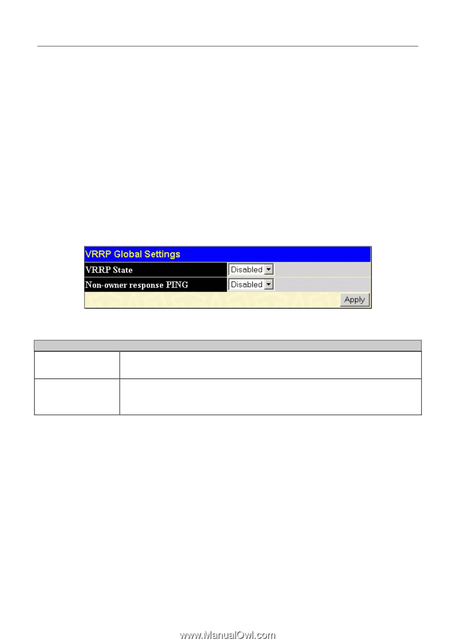
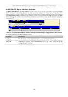
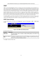
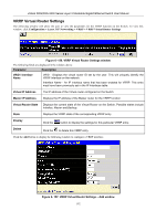
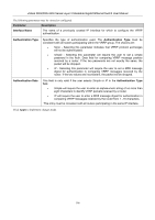
xStack DGS/DXS-3300 Series Layer 3 Stackable Gigabit Ethernet Switch User Manual VRRP VRRP or Virtual Routing Redundancy Protocol is a function on the Switch that dynamically assigns responsibility for a virtual router to one of the VRRP routers on a LAN. The VRRP router that controls the IP address associated with a virtual router is called the Master, and will forward packets sent to this IP address. This will allow any Virtual Router IP address on the LAN to be used as the default first hop router by end hosts. Utilizing VRRP, the administrator can achieve a higher available default path cost without needing to configure every end host for dynamic routing or routing discovery protocols. Statically configured default routes on the LAN are prone to a single point of failure. VRRP is designed to eliminate these failures by setting an election protocol that will assign a responsibility for a virtual router to one of the VRRP routers on the LAN. When a virtual router fails, the election protocol will select a virtual router with the highest priority to be the Master router on the LAN. This retains the link and the connection is kept alive, regardless of the point of failure. To configure VRRP for virtual routers on the Switch, an IP interface must be present on the system and it must be a part of a VLAN. VRRP IP interfaces may be assigned to every VLAN, and therefore IP interface, on the Switch. VRRP routers within the same VRRP group must be consistent in configuration settings for this protocol to function optimally. VRRP Global Settings To enable VRRP globally on the Switch, click Configuration > Layer 3 IP Networking > VRRP > VRRP Global Settings: Figure 6- 155. VRRP Global Settings window The following fields can be set: Parameter Description VRRP State Use the pull-down menu to enable or disable VRRP globally on the Switch. The default is Disabled. Non-owner response Enabling this parameter will allow the virtual IP address to be pinged from other host PING end nodes to verify connectivity. This will only enable the ping connectivity check function. This command is Disabled by default. Click Apply to implement changes made. 191
-
 1
1 -
2
-
3
-
4
-
5
-
6
-
7
-
8
-
9
-
10
-
11
-
12
-
13
-
14
-
15
-
16
-
17
-
18
-
19
-
20
-
21
-
22
-
23
-
24
-
25
-
26
-
27
-
28
-
29
-
30
-
31
-
32
-
33
-
34
-
35
-
36
-
37
-
38
-
39
-
40
-
41
-
42
-
43
-
44
-
45
-
46
-
47
-
48
-
49
-
50
-
51
-
52
-
53
-
54
-
55
-
56
-
57
-
58
-
59
-
60
-
61
-
62
-
63
-
64
-
65
-
66
-
67
-
68
-
69
-
70
-
71
-
72
-
73
-
74
-
75
-
76
-
77
-
78
-
79
-
80
-
81
-
82
-
83
-
84
-
85
-
86
-
87
-
88
-
89
-
90
-
91
-
92
-
93
-
94
-
95
-
96
-
97
-
98
-
99
-
100
-
101
-
102
-
103
-
104
-
105
-
106
-
107
-
108
-
109
-
110
-
111
-
112
-
113
-
114
-
115
-
116
-
117
-
118
-
119
-
120
-
121
-
122
-
123
-
124
-
125
-
126
-
127
-
128
-
129
-
130
-
131
-
132
-
133
-
134
-
135
-
136
-
137
-
138
-
139
-
140
-
141
-
142
-
143
-
144
-
145
-
146
-
147
-
148
-
149
-
150
-
151
-
152
-
153
-
154
-
155
-
156
-
157
-
158
-
159
-
160
-
161
-
162
-
163
-
164
-
165
-
166
-
167
-
168
-
169
-
170
-
171
-
172
-
173
-
174
-
175
-
176
-
177
-
178
-
179
-
180
-
181
-
182
-
183
-
184
-
185
-
186
-
187
-
188
-
189
-
190
-
191
-
192
-
193
-
194
-
195
-
196
-
197
-
198
-
199
-
200
-
 201
201 -
 202
202 -
 203
203 -
 204
204 -
 205
205 -
 206
206 -
 207
207 -
 208
208 -
 209
209 -
 210
210 -
 211
211 -
212
-
213
-
214
-
215
-
216
-
217
-
218
-
219
-
220
-
221
-
222
-
223
-
224
-
225
-
226
-
227
-
228
-
229
-
230
-
231
-
232
-
233
-
234
-
235
-
236
-
237
-
238
-
239
-
240
-
241
-
242
-
243
-
244
-
245
-
246
-
247
-
248
-
249
-
250
-
251
-
252
-
253
-
254
-
255
-
256
-
257
-
258
-
259
-
260
-
261
-
262
-
263
-
264
-
265
-
266
-
267
-
268
-
269
-
270
-
271
-
272
-
273
-
274
-
275
-
276
-
277
-
278
-
279
-
280
-
281
-
282
-
283
-
284
-
285
-
286
-
287
-
288
-
289
-
290
-
291
-
292
-
293
-
294
-
295
-
296
-
297
-
298
-
299
-
300
-
301
-
302
-
303
-
304
-
305
-
306
-
307
-
308
-
309
-
310
-
311
-
312
-
313
-
314
-
315
-
316
-
317
-
318
-
319
-
320
-
321
-
322
-
323
-
324
-
325
-
326
-
327
-
328
-
329
-
330
-
331
-
332
-
333
-
334
-
335
-
336
-
337
-
338
-
339
-
340
-
341
-
342
-
343
-
344
-
345
-
346
-
347
-
348
-
349
-
350
-
351
-
352
-
353
-
354
-
355
-
356
-
357
-
358
-
359
-
360
-
361
-
362
-
363
-
364
-
365
-
366
-
367
-
368
-
369
-
370
-
371
-
372
-
373
-
374
-
375
-
376
-
377
-
378
-
379
-
380
-
381
-
382
-
383
-
384
-
385
-
386
-
387
-
388
-
389
-
390
-
391
-
392
 |
 |