D-Link DGS-3324SR Product Manual - Page 38
Management Options, Web-based Management Interface, SNMP-Based Management - mib
 |
UPC - 790069262067
View all D-Link DGS-3324SR manuals
Add to My Manuals
Save this manual to your list of manuals |
Page 38 highlights
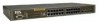
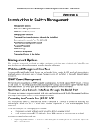
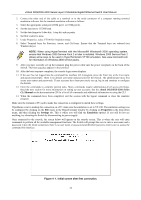
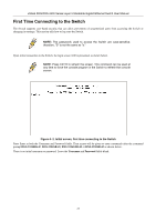
xStack DGS/DXS-3300 Series Layer 3 Stackable Gigabit Ethernet Switch User Manual Section 4 Introduction to Switch Management Management Options Web-based Management Interface SNMP-Based Management Managing User Accounts Command Line Console Interface through the Serial Port Connecting the Console Port (RS-232 DCE) First Time Connecting to the Switch Password Protection SNMP Settings IP Address Assignment Connecting Devices to the Switch Management Options This system may be managed out-of-band through the console port on the front panel or in-band using Telnet. The user may also choose the web-based management, accessible through a web browser. Web-based Management Interface After successfully installing the Switch, the user can configure the Switch, monitor the LED panel, and display statistics graphically using a web browser, such as Netscape Navigator (version 6.2 and higher) or Microsoft® Internet Explorer (version 5.0). SNMP-Based Management The Switch can be managed with an SNMP-compatible console program. The Switch supports SNMP version 1.0, version 2.0 and version 3.0. The SNMP agent decodes the incoming SNMP messages and responds to requests with MIB objects stored in the database. The SNMP agent updates the MIB objects to generate statistics and counters. Command Line Console Interface through the Serial Port The user can also connect a computer or terminal to the serial console port to access the Switch. The command-line-driven interface provides complete access to all Switch management features. Connecting the Console Port (RS-232 DCE) The Switch provides an RS-232 serial port that enables a connection to a computer or terminal for monitoring and configuring the Switch. This port is a female DB-9 connector, implemented as a data terminal equipment (DTE) connection. To use the console port, the following equipment is needed: • A terminal or a computer with both a serial port and the ability to emulate a terminal. • A null modem or crossover RS-232 cable with a female DB-9 connector for the console port on the Switch. To connect a terminal to the console port: 1. Connect the female connector of the RS-232 cable directly to the console port on the Switch, and tighten the captive retaining screws. 23
-
 1
1 -
2
-
3
-
4
-
5
-
6
-
7
-
8
-
9
-
10
-
11
-
12
-
13
-
14
-
15
-
16
-
17
-
18
-
19
-
20
-
21
-
22
-
23
-
24
-
25
-
26
-
27
-
28
-
29
-
30
-
31
-
32
-
 33
33 -
 34
34 -
 35
35 -
 36
36 -
 37
37 -
 38
38 -
 39
39 -
 40
40 -
 41
41 -
 42
42 -
 43
43 -
44
-
45
-
46
-
47
-
48
-
49
-
50
-
51
-
52
-
53
-
54
-
55
-
56
-
57
-
58
-
59
-
60
-
61
-
62
-
63
-
64
-
65
-
66
-
67
-
68
-
69
-
70
-
71
-
72
-
73
-
74
-
75
-
76
-
77
-
78
-
79
-
80
-
81
-
82
-
83
-
84
-
85
-
86
-
87
-
88
-
89
-
90
-
91
-
92
-
93
-
94
-
95
-
96
-
97
-
98
-
99
-
100
-
101
-
102
-
103
-
104
-
105
-
106
-
107
-
108
-
109
-
110
-
111
-
112
-
113
-
114
-
115
-
116
-
117
-
118
-
119
-
120
-
121
-
122
-
123
-
124
-
125
-
126
-
127
-
128
-
129
-
130
-
131
-
132
-
133
-
134
-
135
-
136
-
137
-
138
-
139
-
140
-
141
-
142
-
143
-
144
-
145
-
146
-
147
-
148
-
149
-
150
-
151
-
152
-
153
-
154
-
155
-
156
-
157
-
158
-
159
-
160
-
161
-
162
-
163
-
164
-
165
-
166
-
167
-
168
-
169
-
170
-
171
-
172
-
173
-
174
-
175
-
176
-
177
-
178
-
179
-
180
-
181
-
182
-
183
-
184
-
185
-
186
-
187
-
188
-
189
-
190
-
191
-
192
-
193
-
194
-
195
-
196
-
197
-
198
-
199
-
200
-
201
-
202
-
203
-
204
-
205
-
206
-
207
-
208
-
209
-
210
-
211
-
212
-
213
-
214
-
215
-
216
-
217
-
218
-
219
-
220
-
221
-
222
-
223
-
224
-
225
-
226
-
227
-
228
-
229
-
230
-
231
-
232
-
233
-
234
-
235
-
236
-
237
-
238
-
239
-
240
-
241
-
242
-
243
-
244
-
245
-
246
-
247
-
248
-
249
-
250
-
251
-
252
-
253
-
254
-
255
-
256
-
257
-
258
-
259
-
260
-
261
-
262
-
263
-
264
-
265
-
266
-
267
-
268
-
269
-
270
-
271
-
272
-
273
-
274
-
275
-
276
-
277
-
278
-
279
-
280
-
281
-
282
-
283
-
284
-
285
-
286
-
287
-
288
-
289
-
290
-
291
-
292
-
293
-
294
-
295
-
296
-
297
-
298
-
299
-
300
-
301
-
302
-
303
-
304
-
305
-
306
-
307
-
308
-
309
-
310
-
311
-
312
-
313
-
314
-
315
-
316
-
317
-
318
-
319
-
320
-
321
-
322
-
323
-
324
-
325
-
326
-
327
-
328
-
329
-
330
-
331
-
332
-
333
-
334
-
335
-
336
-
337
-
338
-
339
-
340
-
341
-
342
-
343
-
344
-
345
-
346
-
347
-
348
-
349
-
350
-
351
-
352
-
353
-
354
-
355
-
356
-
357
-
358
-
359
-
360
-
361
-
362
-
363
-
364
-
365
-
366
-
367
-
368
-
369
-
370
-
371
-
372
-
373
-
374
-
375
-
376
-
377
-
378
-
379
-
380
-
381
-
382
-
383
-
384
-
385
-
386
-
387
-
388
-
389
-
390
-
391
-
392
 |
 |