D-Link DGS-3324SR Product Manual - Page 53
Manual, xxx.xxx.xxx.xxx, Subnet Mask, Default, Gateway, VLAN Name, Security IP Management
 |
UPC - 790069262067
View all D-Link DGS-3324SR manuals
Add to My Manuals
Save this manual to your list of manuals |
Page 53 highlights
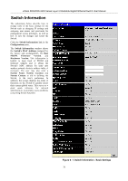
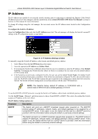
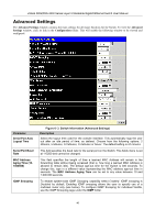
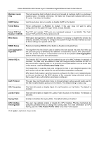
xStack DGS/DXS-3300 Series Layer 3 Stackable Gigabit Ethernet Switch User Manual Manual Allows the entry of an IP address, Subnet Mask, and a Default Gateway for the Switch. These fields should be of the form xxx.xxx.xxx.xxx, where each xxx is a number (represented in decimal form) between 0 and 255. This address should be a unique address on the network assigned for use by the network administrator. Subnet Mask A Bitmask that determines the extent of the subnet that the Switch is on. This Subnet Mask should be of the form xxx.xxx.xxx.xxx, where each xxx is a number (represented in decimal) between 0 and 255. The value should be 255.0.0.0 for a Class A network, 255.255.0.0 for a Class B network, and 255.255.255.0 for a Class C network, but custom subnet masks are allowed. Default Gateway IP address that determines where packets with a destination address outside the current subnet should be sent. This is usually the address of a router or a host acting as an IP gateway. If your network is not part of an intranet, or you do not want the Switch to be accessible outside your local network, leave this field unchanged. VLAN Name This allows the entry of a VLAN Name from which a management station will be allowed to manage the Switch using TCP/IP (in-band via web manager or Telnet). Management stations that are on VLANs other than the one entered here will not be able to manage the Switch in-band unless their IP addresses are entered in the Security IP Management menu. If VLANs have not yet been configured for the Switch, the default VLAN contains all of the Switch's ports. There are no entries in the Security IP Management table, by default, so any management station that can connect to the Switch can access the Switch until a management VLAN is specified or Management Station IP Addresses are assigned. Auto Config State When enabled, Auto Config instructs the Switch to get a configuration file via TFTP, and it becomes a DHCP client automatically. The configuration file will be loaded upon boot up. To use Auto Config, the DHCP server must be set up to deliver the TFTP server IP address and configuration file name information in the DHCP reply packet. The TFTP server must be running and have the requested configuration file stored in its base directory when the request is received from the Switch. Consult the DHCP server and/or TFTP server software instructions for information on loading a configuration file for use by a client. (Also, see the section titled "Maintenance" for instructions on uploading a configuration to a TFTP server.) If the Switch is unable to complete the auto configuration process, the previously saved configuration file present in Switch memory will be loaded. Click Apply to implement changes made. 38
-
 1
1 -
2
-
3
-
4
-
5
-
6
-
7
-
8
-
9
-
10
-
11
-
12
-
13
-
14
-
15
-
16
-
17
-
18
-
19
-
20
-
21
-
22
-
23
-
24
-
25
-
26
-
27
-
28
-
29
-
30
-
31
-
32
-
33
-
34
-
35
-
36
-
37
-
38
-
39
-
40
-
41
-
42
-
43
-
44
-
45
-
46
-
47
-
 48
48 -
 49
49 -
 50
50 -
 51
51 -
 52
52 -
 53
53 -
 54
54 -
 55
55 -
 56
56 -
 57
57 -
 58
58 -
59
-
60
-
61
-
62
-
63
-
64
-
65
-
66
-
67
-
68
-
69
-
70
-
71
-
72
-
73
-
74
-
75
-
76
-
77
-
78
-
79
-
80
-
81
-
82
-
83
-
84
-
85
-
86
-
87
-
88
-
89
-
90
-
91
-
92
-
93
-
94
-
95
-
96
-
97
-
98
-
99
-
100
-
101
-
102
-
103
-
104
-
105
-
106
-
107
-
108
-
109
-
110
-
111
-
112
-
113
-
114
-
115
-
116
-
117
-
118
-
119
-
120
-
121
-
122
-
123
-
124
-
125
-
126
-
127
-
128
-
129
-
130
-
131
-
132
-
133
-
134
-
135
-
136
-
137
-
138
-
139
-
140
-
141
-
142
-
143
-
144
-
145
-
146
-
147
-
148
-
149
-
150
-
151
-
152
-
153
-
154
-
155
-
156
-
157
-
158
-
159
-
160
-
161
-
162
-
163
-
164
-
165
-
166
-
167
-
168
-
169
-
170
-
171
-
172
-
173
-
174
-
175
-
176
-
177
-
178
-
179
-
180
-
181
-
182
-
183
-
184
-
185
-
186
-
187
-
188
-
189
-
190
-
191
-
192
-
193
-
194
-
195
-
196
-
197
-
198
-
199
-
200
-
201
-
202
-
203
-
204
-
205
-
206
-
207
-
208
-
209
-
210
-
211
-
212
-
213
-
214
-
215
-
216
-
217
-
218
-
219
-
220
-
221
-
222
-
223
-
224
-
225
-
226
-
227
-
228
-
229
-
230
-
231
-
232
-
233
-
234
-
235
-
236
-
237
-
238
-
239
-
240
-
241
-
242
-
243
-
244
-
245
-
246
-
247
-
248
-
249
-
250
-
251
-
252
-
253
-
254
-
255
-
256
-
257
-
258
-
259
-
260
-
261
-
262
-
263
-
264
-
265
-
266
-
267
-
268
-
269
-
270
-
271
-
272
-
273
-
274
-
275
-
276
-
277
-
278
-
279
-
280
-
281
-
282
-
283
-
284
-
285
-
286
-
287
-
288
-
289
-
290
-
291
-
292
-
293
-
294
-
295
-
296
-
297
-
298
-
299
-
300
-
301
-
302
-
303
-
304
-
305
-
306
-
307
-
308
-
309
-
310
-
311
-
312
-
313
-
314
-
315
-
316
-
317
-
318
-
319
-
320
-
321
-
322
-
323
-
324
-
325
-
326
-
327
-
328
-
329
-
330
-
331
-
332
-
333
-
334
-
335
-
336
-
337
-
338
-
339
-
340
-
341
-
342
-
343
-
344
-
345
-
346
-
347
-
348
-
349
-
350
-
351
-
352
-
353
-
354
-
355
-
356
-
357
-
358
-
359
-
360
-
361
-
362
-
363
-
364
-
365
-
366
-
367
-
368
-
369
-
370
-
371
-
372
-
373
-
374
-
375
-
376
-
377
-
378
-
379
-
380
-
381
-
382
-
383
-
384
-
385
-
386
-
387
-
388
-
389
-
390
-
391
-
392
 |
 |