IBM 84885BU User Manual - Page 14
Server, controls, connectors, power, Front
 |
View all IBM 84885BU manuals
Add to My Manuals
Save this manual to your list of manuals |
Page 14 highlights
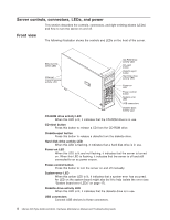
Server controls, connectors, LEDs, and power This section describes the controls, connectors, and light-emitting diodes (LEDs) and how to turn the server on and off. Front view The following illustration shows the controls and LEDs on the front of the server. Ethernet link status LED Ethernet transmit/receive activity LED CD-ROM drive activity LED CD-eject button Diskette-eject button Hard disk drive activity LED Power-on LED Power-control button System error LED USB connectors Diskette drive activity LED CD-ROM drive activity LED When this LED is lit, it indicates that the CD-ROM drive is in use. CD-eject button Press this button to release a CD from the CD-ROM drive. Diskette-eject button Press this button to release a diskette from the diskette drive. Hard disk drive activity LED When this LED is flashing, it indicates that a hard disk drive is in use. Power-on LED When this LED is lit and not flashing, it indicates that the server is turned on. When this LED is flashing, it indicates that the server is off and still connected to an ac power source. Power-control button Press this button to turn the server on and off manually. System-error LED When this amber LED is lit, it indicates that a system error has occurred. An LED on the system board might also be lit to help isolate the error (see "System board error LEDs" on page 17). Diskette drive activity LED When this LED is lit, it indicates that the diskette drive is in use. USB connectors Connect USB devices to these connectors. 4 xSeries 226 Type 8488 and 8648: Hardware Maintenance Manual and Troubleshooting Guide
-
 1
1 -
2
-
3
-
4
-
5
-
6
-
7
-
8
-
 9
9 -
 10
10 -
 11
11 -
 12
12 -
 13
13 -
 14
14 -
 15
15 -
 16
16 -
 17
17 -
 18
18 -
 19
19 -
20
-
21
-
22
-
23
-
24
-
25
-
26
-
27
-
28
-
29
-
30
-
31
-
32
-
33
-
34
-
35
-
36
-
37
-
38
-
39
-
40
-
41
-
42
-
43
-
44
-
45
-
46
-
47
-
48
-
49
-
50
-
51
-
52
-
53
-
54
-
55
-
56
-
57
-
58
-
59
-
60
-
61
-
62
-
63
-
64
-
65
-
66
-
67
-
68
-
69
-
70
-
71
-
72
-
73
-
74
-
75
-
76
-
77
-
78
-
79
-
80
-
81
-
82
-
83
-
84
-
85
-
86
-
87
-
88
-
89
-
90
-
91
-
92
-
93
-
94
-
95
-
96
-
97
-
98
-
99
-
100
-
101
-
102
-
103
-
104
-
105
-
106
-
107
-
108
-
109
-
110
-
111
-
112
-
113
-
114
-
115
-
116
-
117
-
118
-
119
-
120
-
121
-
122
-
123
-
124
-
125
-
126
-
127
-
128
-
129
-
130
-
131
-
132
-
133
-
134
-
135
-
136
-
137
-
138
-
139
-
140
-
141
-
142
-
143
-
144
-
145
-
146
-
147
-
148
-
149
-
150
-
151
-
152
-
153
-
154
-
155
-
156
-
157
-
158
-
159
-
160
-
161
-
162
-
163
-
164
-
165
-
166
-
167
-
168
-
169
-
170
-
171
-
172
-
173
-
174
-
175
-
176
-
177
-
178
-
179
-
180
-
181
-
182
-
183
-
184
-
185
-
186
-
187
-
188
-
189
-
190
-
191
-
192
-
193
-
194
-
195
-
196
-
197
-
198
-
199
-
200
 |
 |
