IBM 84885BU User Manual - Page 28
drive, Recovering, POST/BIOS, update, failure
 |
View all IBM 84885BU manuals
Add to My Manuals
Save this manual to your list of manuals |
Page 28 highlights
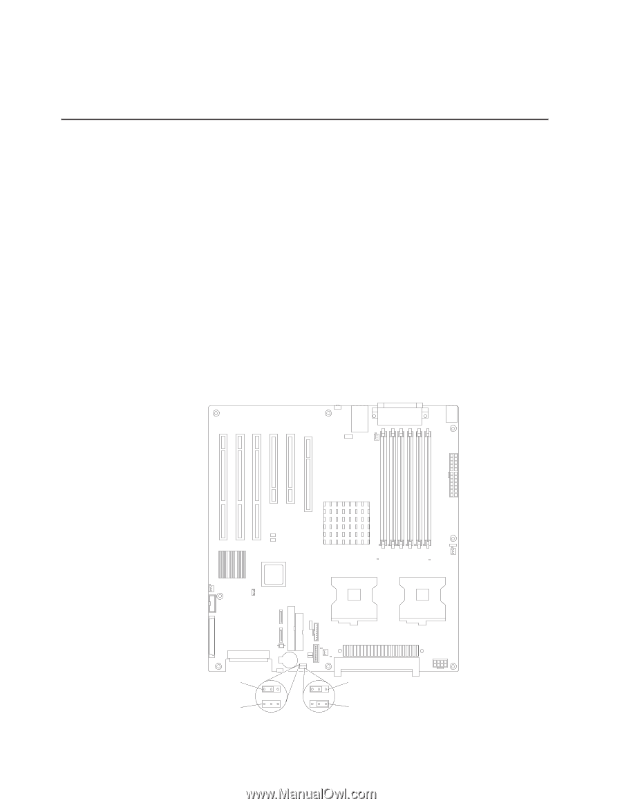
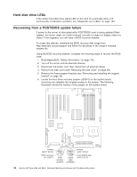
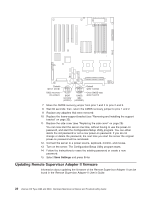
Hard disk drive LEDs If the amber hard disk drive status LED on the front of a hard disk drive is lit continuously, it indicates a problem; see "Diagnostic error LEDs" on page 109. Recovering from a POST/BIOS update failure If power to the server is interrupted while POST/BIOS code is being updated (flash update), the server might not restart (reboot) correctly or might not display video (no video). If this happens, you will need a BIOS recovery diskette. To create this diskette, download the BIOS recovery disk image from http://www.ibm.com/pc/support and follow the directions in the image's included readme file. Using the BIOS recovery diskette, complete the following steps to recover the BIOS code: 1. Read Appendix B, "Safety information," on page 143. 2. Turn off the server and all attached devices. 3. Disconnect the power cord; then, disconnect all external cables. 4. Remove the side cover (see "Removing the side cover" on page 28). 5. Remove the frame-support bracket (see "Removing and installing the support bracket" on page 32). 6. Locate the boot block recovery jumper (JCON1) on the system board, removing any adapters that impede access to the jumper. The following illustration shows the location of the jumper on the system board. Default (pins 1 and 2) BIOS recovery (no jumper) 1 2 3 BIOS recovery (JCON1) 1 2 3 CMOS data (JCMOS1) Default (pins 1 and 2) Clear CMOS data (pins 2 and 3) 18 xSeries 226 Type 8488 and 8648: Hardware Maintenance Manual and Troubleshooting Guide
-
 1
1 -
2
-
3
-
4
-
5
-
6
-
7
-
8
-
9
-
10
-
11
-
12
-
13
-
14
-
15
-
16
-
17
-
18
-
19
-
20
-
21
-
22
-
 23
23 -
 24
24 -
 25
25 -
 26
26 -
 27
27 -
 28
28 -
 29
29 -
 30
30 -
 31
31 -
 32
32 -
 33
33 -
34
-
35
-
36
-
37
-
38
-
39
-
40
-
41
-
42
-
43
-
44
-
45
-
46
-
47
-
48
-
49
-
50
-
51
-
52
-
53
-
54
-
55
-
56
-
57
-
58
-
59
-
60
-
61
-
62
-
63
-
64
-
65
-
66
-
67
-
68
-
69
-
70
-
71
-
72
-
73
-
74
-
75
-
76
-
77
-
78
-
79
-
80
-
81
-
82
-
83
-
84
-
85
-
86
-
87
-
88
-
89
-
90
-
91
-
92
-
93
-
94
-
95
-
96
-
97
-
98
-
99
-
100
-
101
-
102
-
103
-
104
-
105
-
106
-
107
-
108
-
109
-
110
-
111
-
112
-
113
-
114
-
115
-
116
-
117
-
118
-
119
-
120
-
121
-
122
-
123
-
124
-
125
-
126
-
127
-
128
-
129
-
130
-
131
-
132
-
133
-
134
-
135
-
136
-
137
-
138
-
139
-
140
-
141
-
142
-
143
-
144
-
145
-
146
-
147
-
148
-
149
-
150
-
151
-
152
-
153
-
154
-
155
-
156
-
157
-
158
-
159
-
160
-
161
-
162
-
163
-
164
-
165
-
166
-
167
-
168
-
169
-
170
-
171
-
172
-
173
-
174
-
175
-
176
-
177
-
178
-
179
-
180
-
181
-
182
-
183
-
184
-
185
-
186
-
187
-
188
-
189
-
190
-
191
-
192
-
193
-
194
-
195
-
196
-
197
-
198
-
199
-
200
 |
 |