IBM 84885BU User Manual - Page 77
Field, replaceable, units
 |
View all IBM 84885BU manuals
Add to My Manuals
Save this manual to your list of manuals |
Page 77 highlights
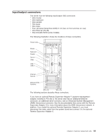
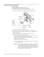
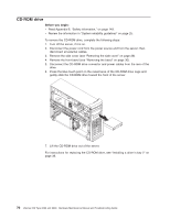
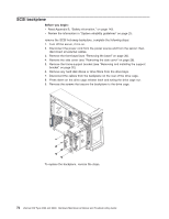
Chapter 5. Field replaceable units Microprocessor air baffle 67 Microprocessor and heat sink 68 CD-ROM drive 70 Diskette drive 71 SCSI backplane 72 Non-hot swap power supply 73 Hot-swap power-supply cage 75 Rear-adapter retainer 77 Front fan 78 Rear fans 80 Power/LED switch assembly 81 Front USB connector assembly 83 System board 85 System board option connectors 85 System board internal connectors 86 System board external connectors 87 System board error LEDs 88 System board jumpers and switches 89 Removing the system board 90 Top/side cover 92 Bezel-release latch 93 Handle assembly 95 The following information describes procedures for removing and installing certain components inside the system. Only a qualified service technician is authorized to replace the components described in this section. Important: The field replaceable unit (FRU) procedures are intended for trained servicers who are familiar with IBM xSeries products. See the parts listing in "System replaceable units" on page 131 to determine if the component being replaced is a customer replaceable unit (CRU) or a FRU. Note: Before servicing this system, read "Installation guidelines" on page 25 and Appendix B, "Safety information," on page 143. Microprocessor air baffle The microprocessor air baffle is held in place by two tabs that protrude through slots in the rear of the server. Complete the following steps to remove the microprocessor air baffle: 1. Open the microprocessor air baffle. 2. At the rear chassis wall, press the sides of the microprocessor air baffle toward each other and move the baffle toward the front of the server. 3. Lift the guide up and out of the server. © Copyright IBM Corp. 2004 67
-
 1
1 -
2
-
3
-
4
-
5
-
6
-
7
-
8
-
9
-
10
-
11
-
12
-
13
-
14
-
15
-
16
-
17
-
18
-
19
-
20
-
21
-
22
-
23
-
24
-
25
-
26
-
27
-
28
-
29
-
30
-
31
-
32
-
33
-
34
-
35
-
36
-
37
-
38
-
39
-
40
-
41
-
42
-
43
-
44
-
45
-
46
-
47
-
48
-
49
-
50
-
51
-
52
-
53
-
54
-
55
-
56
-
57
-
58
-
59
-
60
-
61
-
62
-
63
-
64
-
65
-
66
-
67
-
68
-
69
-
70
-
71
-
 72
72 -
 73
73 -
 74
74 -
 75
75 -
 76
76 -
 77
77 -
 78
78 -
 79
79 -
 80
80 -
 81
81 -
 82
82 -
83
-
84
-
85
-
86
-
87
-
88
-
89
-
90
-
91
-
92
-
93
-
94
-
95
-
96
-
97
-
98
-
99
-
100
-
101
-
102
-
103
-
104
-
105
-
106
-
107
-
108
-
109
-
110
-
111
-
112
-
113
-
114
-
115
-
116
-
117
-
118
-
119
-
120
-
121
-
122
-
123
-
124
-
125
-
126
-
127
-
128
-
129
-
130
-
131
-
132
-
133
-
134
-
135
-
136
-
137
-
138
-
139
-
140
-
141
-
142
-
143
-
144
-
145
-
146
-
147
-
148
-
149
-
150
-
151
-
152
-
153
-
154
-
155
-
156
-
157
-
158
-
159
-
160
-
161
-
162
-
163
-
164
-
165
-
166
-
167
-
168
-
169
-
170
-
171
-
172
-
173
-
174
-
175
-
176
-
177
-
178
-
179
-
180
-
181
-
182
-
183
-
184
-
185
-
186
-
187
-
188
-
189
-
190
-
191
-
192
-
193
-
194
-
195
-
196
-
197
-
198
-
199
-
200
 |
 |