IBM 84885BU User Manual - Page 27
Diagnostic, error, System, board
 |
View all IBM 84885BU manuals
Add to My Manuals
Save this manual to your list of manuals |
Page 27 highlights
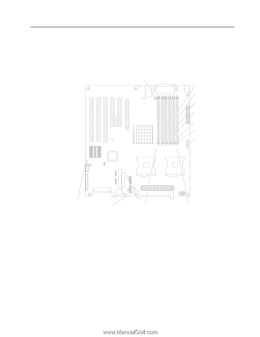
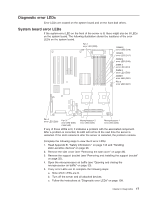
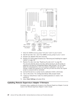
Diagnostic error LEDs Error LEDs are located on the system board and on the hard disk drives. System board error LEDs If the system-error LED on the front of the server is lit, there might also be lit LEDs on the system board. The following illustration shows the locations of the error LEDs on the system board. Fan 1 error LED (D26) DIMM 6 error LED (D16) DIMM 5 error LED (D17) DIMM 4 error LED (D18) DIMM 3 error LED (D19) DIMM 2 error LED (D20) DIMM 1 error LED (D21) Fan 2 error LED (D27) Fan 4 error LED (D29) Fan 3 error LED (D25) (reserved) Microprocessor 2 error LED (D22) Microprocessor 1 error LED (D23) If any of these LEDs is lit, it indicates a problem with the associated component. After a problem is corrected, its LED will not be lit the next time the server is restarted. If the LED remains lit after the server is restarted, the problem remains. Complete the following steps to view the lit error LEDs: 1. Read Appendix B, "Safety information," on page 143 and "Handling static-sensitive devices" on page 26. 2. Remove the side cover (see "Removing the side cover" on page 28). 3. Remove the support bracket (see "Removing and installing the support bracket" on page 32). 4. Open the microprocessor air baffle (see "Opening and closing the microprocessor air baffle" on page 33). 5. If any error LEDs are lit, complete the following steps: a. Note which LEDs are lit. b. Turn off the server and all attached devices. c. Follow the instructions at "Diagnostic error LEDs" on page 109. Chapter 3. Diagnostics 17
-
 1
1 -
2
-
3
-
4
-
5
-
6
-
7
-
8
-
9
-
10
-
11
-
12
-
13
-
14
-
15
-
16
-
17
-
18
-
19
-
20
-
21
-
 22
22 -
 23
23 -
 24
24 -
 25
25 -
 26
26 -
 27
27 -
 28
28 -
 29
29 -
 30
30 -
 31
31 -
 32
32 -
33
-
34
-
35
-
36
-
37
-
38
-
39
-
40
-
41
-
42
-
43
-
44
-
45
-
46
-
47
-
48
-
49
-
50
-
51
-
52
-
53
-
54
-
55
-
56
-
57
-
58
-
59
-
60
-
61
-
62
-
63
-
64
-
65
-
66
-
67
-
68
-
69
-
70
-
71
-
72
-
73
-
74
-
75
-
76
-
77
-
78
-
79
-
80
-
81
-
82
-
83
-
84
-
85
-
86
-
87
-
88
-
89
-
90
-
91
-
92
-
93
-
94
-
95
-
96
-
97
-
98
-
99
-
100
-
101
-
102
-
103
-
104
-
105
-
106
-
107
-
108
-
109
-
110
-
111
-
112
-
113
-
114
-
115
-
116
-
117
-
118
-
119
-
120
-
121
-
122
-
123
-
124
-
125
-
126
-
127
-
128
-
129
-
130
-
131
-
132
-
133
-
134
-
135
-
136
-
137
-
138
-
139
-
140
-
141
-
142
-
143
-
144
-
145
-
146
-
147
-
148
-
149
-
150
-
151
-
152
-
153
-
154
-
155
-
156
-
157
-
158
-
159
-
160
-
161
-
162
-
163
-
164
-
165
-
166
-
167
-
168
-
169
-
170
-
171
-
172
-
173
-
174
-
175
-
176
-
177
-
178
-
179
-
180
-
181
-
182
-
183
-
184
-
185
-
186
-
187
-
188
-
189
-
190
-
191
-
192
-
193
-
194
-
195
-
196
-
197
-
198
-
199
-
200
 |
 |