IBM 84885BU User Manual - Page 56
Installing, additional, microprocessor
 |
View all IBM 84885BU manuals
Add to My Manuals
Save this manual to your list of manuals |
Page 56 highlights
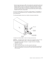
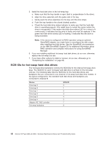
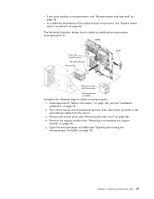
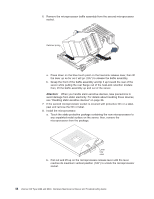
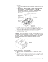
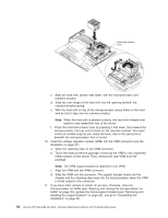
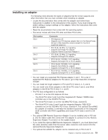
4. Open the front adapter-support bracket and remove the rear adapter-retention bracket from the PCI-X slots (see "Installing an adapter" on page 51 for instructions). You might also have to remove longer adapters for access to the SCSI connectors on the system board. 5. Connect the SCSI signal cable end labeled "PLANAR" to the connector for SCSI channel B on the system board (see "System board internal connectors" on page 86 for the location of the SCSI channel B connector). 6. Route the SCSI cable to the adapter slot that has the special SCSI-knockout slot cover on the back of the server (see "Connecting the cables" on page 61 for an illustration of the SCSI-knockout slot cover, normally in PCI slot 3). Make sure the cable does not block the flow of air to the hard disk drives. Note: You can move the special SCSI-knockout slot cover to a different slot if needed. 7. Remove the SCSI-connector knockout from the PCI-X slot cover; then, insert the external SCSI connector on the SCSI cable into the knockout opening and secure it with the attached screws. 8. Replace any adapters you removed in step 4. Close the front adapter-support bracket and replace the rear adapter-retention bracket. 9. Replace the support bracket (see "Removing and installing the support bracket" on page 32). 10. Replace the cover (see "Replacing the side cover" on page 29). 11. Reconnect the external cables and power cords. Turn on the attached devices, and turn on the server. 12. Use the SCSISelect program to configure SCSI channel B (see the User's Guide for information about using the SCSISelect program). Installing an additional microprocessor The following notes describe the type of microprocessor that the server supports and other information that you must consider when installing a microprocessor: v The server comes with one microprocessor and supports up to two microprocessors. v Read the documentation that comes with the microprocessor to determine whether you must update the basic input/output system (BIOS) code in the server. To download the most current level of BIOS code for the server, go to http://www.ibm.com/pc/support/. v (Optional) Obtain an SMP-capable operating system. For a list of supported operating systems, go to http://www.ibm.com/pc/compat/. v The microprocessors must have the same cache size and type, and the same clock speed. Microprocessor internal and external clock frequencies must be identical. You can use the Configuration/Setup Utility program to determine the specific type of microprocessor that is in the server. v Terminator cards are not required for empty microprocessor sockets. However, for airflow, an empty microprocessor socket must contain a microprocessor baffle. v The microprocessor speeds are automatically set for this server; therefore, you do not have to set any microprocessor frequency-selection jumpers or switches. v The system board contains an integrated voltage regulator for microprocessor 1; you must install a voltage regulator module (VRM) on the system board when you install microprocessor 2. The VRM comes in the microprocessor option kit. v These instructions assume that you are installing microprocessor 2. 46 xSeries 226 Type 8488 and 8648: Hardware Maintenance Manual and Troubleshooting Guide
-
 1
1 -
2
-
3
-
4
-
5
-
6
-
7
-
8
-
9
-
10
-
11
-
12
-
13
-
14
-
15
-
16
-
17
-
18
-
19
-
20
-
21
-
22
-
23
-
24
-
25
-
26
-
27
-
28
-
29
-
30
-
31
-
32
-
33
-
34
-
35
-
36
-
37
-
38
-
39
-
40
-
41
-
42
-
43
-
44
-
45
-
46
-
47
-
48
-
49
-
50
-
 51
51 -
 52
52 -
 53
53 -
 54
54 -
 55
55 -
 56
56 -
 57
57 -
 58
58 -
 59
59 -
 60
60 -
 61
61 -
62
-
63
-
64
-
65
-
66
-
67
-
68
-
69
-
70
-
71
-
72
-
73
-
74
-
75
-
76
-
77
-
78
-
79
-
80
-
81
-
82
-
83
-
84
-
85
-
86
-
87
-
88
-
89
-
90
-
91
-
92
-
93
-
94
-
95
-
96
-
97
-
98
-
99
-
100
-
101
-
102
-
103
-
104
-
105
-
106
-
107
-
108
-
109
-
110
-
111
-
112
-
113
-
114
-
115
-
116
-
117
-
118
-
119
-
120
-
121
-
122
-
123
-
124
-
125
-
126
-
127
-
128
-
129
-
130
-
131
-
132
-
133
-
134
-
135
-
136
-
137
-
138
-
139
-
140
-
141
-
142
-
143
-
144
-
145
-
146
-
147
-
148
-
149
-
150
-
151
-
152
-
153
-
154
-
155
-
156
-
157
-
158
-
159
-
160
-
161
-
162
-
163
-
164
-
165
-
166
-
167
-
168
-
169
-
170
-
171
-
172
-
173
-
174
-
175
-
176
-
177
-
178
-
179
-
180
-
181
-
182
-
183
-
184
-
185
-
186
-
187
-
188
-
189
-
190
-
191
-
192
-
193
-
194
-
195
-
196
-
197
-
198
-
199
-
200
 |
 |