IBM 84885BU User Manual - Page 74
Auxiliary-device, pointing-device, connector, Ethernet, RJ-45, Keyboard, Parallel
 |
View all IBM 84885BU manuals
Add to My Manuals
Save this manual to your list of manuals |
Page 74 highlights
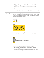
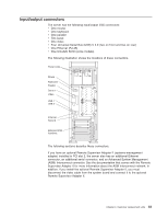
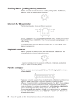
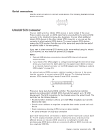
Auxiliary-device (pointing-device) connector Use this connector to connect a mouse or other pointing device. The following illustration shows an auxiliary-device connector. 6 4 2 5 3 1 Ethernet (RJ-45) connector The following illustration shows an Ethernet connector. Activity LED (green) Link LED (green) 8 1 Connect a Category 3, 4, or 5 unshielded twisted-pair (UTP) cable to this connector. The 100BASE-TX and 1000BASE-T Fast Ethernet standards require Category 5 or higher cabling. For more information about the Ethernet controller, see the User's Guide on the IBM Documentation CD. Keyboard connector Use this connector to connect a PS/2 (non-USB) keyboard to the server. The following illustration shows a keyboard connector. 6 5 4 3 2 1 If you attach a keyboard to this connector, USB ports and devices are disabled during the power-on self-test (POST). Parallel connector Use this connector to connect a parallel device. The following illustration shows a parallel connector. 13 1 25 14 The parallel connector supports three standard Institute of Electrical and Electronics Engineers (IEEE) 1284 modes of operation: Standard Parallel Port (SPP), Enhanced Parallel Port (EPP), and Extended Capability Port (ECP). If you configure the parallel port to operate in bidirectional mode, it supports the ECP and EPP modes of operation. To configure the parallel port, use the Devices and I/O Ports option in the Configuration/Setup Utility program (see "Starting the Configuration/Setup Utility program" on page 10). If you configure the parallel port to operate in bidirectional mode, use an IEEE 1284-compliant cable that does not exceed 3 meters (9.8 ft). 64 xSeries 226 Type 8488 and 8648: Hardware Maintenance Manual and Troubleshooting Guide
-
 1
1 -
2
-
3
-
4
-
5
-
6
-
7
-
8
-
9
-
10
-
11
-
12
-
13
-
14
-
15
-
16
-
17
-
18
-
19
-
20
-
21
-
22
-
23
-
24
-
25
-
26
-
27
-
28
-
29
-
30
-
31
-
32
-
33
-
34
-
35
-
36
-
37
-
38
-
39
-
40
-
41
-
42
-
43
-
44
-
45
-
46
-
47
-
48
-
49
-
50
-
51
-
52
-
53
-
54
-
55
-
56
-
57
-
58
-
59
-
60
-
61
-
62
-
63
-
64
-
65
-
66
-
67
-
68
-
 69
69 -
 70
70 -
 71
71 -
 72
72 -
 73
73 -
 74
74 -
 75
75 -
 76
76 -
 77
77 -
 78
78 -
 79
79 -
80
-
81
-
82
-
83
-
84
-
85
-
86
-
87
-
88
-
89
-
90
-
91
-
92
-
93
-
94
-
95
-
96
-
97
-
98
-
99
-
100
-
101
-
102
-
103
-
104
-
105
-
106
-
107
-
108
-
109
-
110
-
111
-
112
-
113
-
114
-
115
-
116
-
117
-
118
-
119
-
120
-
121
-
122
-
123
-
124
-
125
-
126
-
127
-
128
-
129
-
130
-
131
-
132
-
133
-
134
-
135
-
136
-
137
-
138
-
139
-
140
-
141
-
142
-
143
-
144
-
145
-
146
-
147
-
148
-
149
-
150
-
151
-
152
-
153
-
154
-
155
-
156
-
157
-
158
-
159
-
160
-
161
-
162
-
163
-
164
-
165
-
166
-
167
-
168
-
169
-
170
-
171
-
172
-
173
-
174
-
175
-
176
-
177
-
178
-
179
-
180
-
181
-
182
-
183
-
184
-
185
-
186
-
187
-
188
-
189
-
190
-
191
-
192
-
193
-
194
-
195
-
196
-
197
-
198
-
199
-
200
 |
 |