IBM 84885BU User Manual - Page 93
Front, connector, assembly
 |
View all IBM 84885BU manuals
Add to My Manuals
Save this manual to your list of manuals |
Page 93 highlights
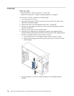
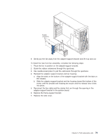
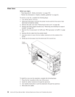
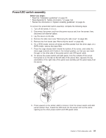
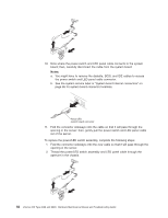
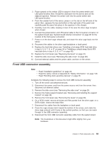
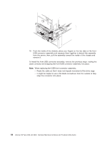
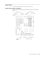
3. Press upward on the amber LED to remove it from the power-switch and LED-panel bracket; then, thread the LED back into the server and out the adjacent aperture. Reinsert the amber LED into the power-switch and LED-panel bracket. 4. From the outside front of the server, press in on the tab on the left side of the panel; then, squeeze the top and bottom of the right side of the panel and carefully push the panel into place in the aperture in the chassis. 5. Carefully route the cable, keeping it clear of the area the drive cage occupies when closed. 6. Connect the power-button and LED-panel cable to the front-panel connector on the system board (see "System board internal connectors" on page 86 for the location of the front-panel connector). 7. Press in on the drive-cage release tab, and rotate the drive cage back into the server. 8. Reconnect the cables to the drive cage backplane or back panel. 9. Replace the hard disk drives (see "Installing a hot-swap SCSI hard disk drive in bay 4, 5, 6, 7, 8, or 9" on page 40 or "Installing a simple-swap Serial ATA hard disk drive in bay 4, 5, 6, or 7" on page 43). 10. Replace the front bezel (see "Replacing the bezel" on page 31). 11. Install the side cover (see "Removing the side cover" on page 28). 12. Connect external cables and the power cable, and turn on the server. Front USB connector assembly Note: v Read "Installation guidelines" on page 25. v Read the safety notices at Appendix B, "Safety information," on page 143. v Read "Handling static-sensitive devices" on page 26. Complete the following steps to remove the front USB connector assembly: 1. Turn off the server and attached devices. 2. Disconnect the power cord from the power source and from the server; then, disconnect all external cables. 3. Remove the side cover (see "Removing the side cover" on page 28. 4. Remove the frame-support bracket (see "Removing and installing the support bracket" on page 32). 5. Remove the front bezel (see "Removing the bezel" on page 30). 6. On a SCSI model, remove all drives and filler panels from the drive cage; on a SATA model, remove the bezel filler. 7. Disconnect the cables from the backplane or back panel. 8. Press the cage-release latch toward the bottom of the server, and rotate the drive cage outward until it locks in the vertical position, so that you can reach through to the USB connector assembly. 9. Disconnect the front USB connector assembly cable from the system board. Note: The illustrations in this document might differ slightly from your hardware. Chapter 5. Field replaceable units 83
-
 1
1 -
2
-
3
-
4
-
5
-
6
-
7
-
8
-
9
-
10
-
11
-
12
-
13
-
14
-
15
-
16
-
17
-
18
-
19
-
20
-
21
-
22
-
23
-
24
-
25
-
26
-
27
-
28
-
29
-
30
-
31
-
32
-
33
-
34
-
35
-
36
-
37
-
38
-
39
-
40
-
41
-
42
-
43
-
44
-
45
-
46
-
47
-
48
-
49
-
50
-
51
-
52
-
53
-
54
-
55
-
56
-
57
-
58
-
59
-
60
-
61
-
62
-
63
-
64
-
65
-
66
-
67
-
68
-
69
-
70
-
71
-
72
-
73
-
74
-
75
-
76
-
77
-
78
-
79
-
80
-
81
-
82
-
83
-
84
-
85
-
86
-
87
-
 88
88 -
 89
89 -
 90
90 -
 91
91 -
 92
92 -
 93
93 -
 94
94 -
 95
95 -
 96
96 -
 97
97 -
 98
98 -
99
-
100
-
101
-
102
-
103
-
104
-
105
-
106
-
107
-
108
-
109
-
110
-
111
-
112
-
113
-
114
-
115
-
116
-
117
-
118
-
119
-
120
-
121
-
122
-
123
-
124
-
125
-
126
-
127
-
128
-
129
-
130
-
131
-
132
-
133
-
134
-
135
-
136
-
137
-
138
-
139
-
140
-
141
-
142
-
143
-
144
-
145
-
146
-
147
-
148
-
149
-
150
-
151
-
152
-
153
-
154
-
155
-
156
-
157
-
158
-
159
-
160
-
161
-
162
-
163
-
164
-
165
-
166
-
167
-
168
-
169
-
170
-
171
-
172
-
173
-
174
-
175
-
176
-
177
-
178
-
179
-
180
-
181
-
182
-
183
-
184
-
185
-
186
-
187
-
188
-
189
-
190
-
191
-
192
-
193
-
194
-
195
-
196
-
197
-
198
-
199
-
200
 |
 |