IBM 84885BU User Manual - Page 50
Installing, hot-swap, drive
 |
View all IBM 84885BU manuals
Add to My Manuals
Save this manual to your list of manuals |
Page 50 highlights
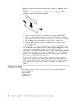
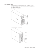
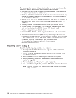
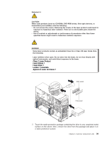
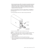
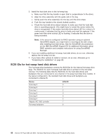
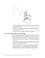
8. Set any jumpers or switches on the drive according to the documentation that comes with the drive. Note: You might find it easier to install the new drive from the front and then attach the cables. 9. If you are installing a 3.5-in. drive in bay 2, attach the 5.25-in. conversion kit, which you can order from IBM, to the 3.5-in. drive. 10. Remove the large drive clip from the side of the drive cage for bays 1 through 3. Slide the drive clip toward the rear of the server; then, snap the drive clip into the screw holes on the side of the drive or conversion kit. 11. Slide the drive into the drive bay until it snaps in place. 12. Determine whether the drive is an IDE or SCSI device; then, connect one end of the applicable signal cable into the back of the drive and make sure that the other end of this cable is connected into the applicable IDE or SCSI connector on the system board. v If you are installing a SCSI removable-media drive, use the one-drop SCSI cable that comes with the drive and connect it to SCSI channel A (SCSI1). See "Power and signal cables for internal drives" on page 44 for additional information about cabling drives and "System board internal connectors" on page 86 for the location of IDE and SCSI connectors on the system board. v If there are open connectors on the cable connecting an existing IDE drive, you can use this cable to connect the new drive. The 4-connector SCSI cable that comes with non-hot-swap model servers cannot be used to connect a SCSI drive in bay 2. 13. Route the signal cable so that it does not block the airflow to the rear of the drives or over the microprocessor and memory. 14. If you have another drive to install or remove, do so now. 15. If you have other options to install or remove, do so now; otherwise, replace the support bracket (see "Removing and installing the support bracket" on page 32), replace the bezel (see "Replacing the bezel" on page 31), and then go to "Completing the installation" on page 60 Installing a hot-swap SCSI hard disk drive in bay 4, 5, 6, 7, 8, or 9 Some server models support hot-swap hard disk drives. The SCSI ID for each hot-swap hard disk drive is printed on the hot-swap lock bar. Before you install a hot-swap hard disk drive, read the following information: v Inspect the drive tray for signs of damage. v Make sure that the drive is correctly installed in the tray. v To maintain proper system cooling, do not operate the server for more than 10 minutes without either a drive or a filler panel installed in each drive bay. v All hot-swap drives in the server must have the same speed rating; if you mix speed ratings, all drives will operate at the speed of the slowest drive. v You do not have to turn off the server to install hot-swap drives in the hot-swap drive bays. v Set the drive jumpers either to disable auto-start or to delay startup, to prevent overtaxing the system power supply by all drives trying to spin up at once. v Install hot-swap hard disk drives in this sequence: bay 9, bay 8, bay 7, bay 6, bay 5, and bay 4. v If the server has an optional RAID adapter, see the documentation that comes with the adapter for instructions for installing a hard disk drive. 40 xSeries 226 Type 8488 and 8648: Hardware Maintenance Manual and Troubleshooting Guide
-
 1
1 -
2
-
3
-
4
-
5
-
6
-
7
-
8
-
9
-
10
-
11
-
12
-
13
-
14
-
15
-
16
-
17
-
18
-
19
-
20
-
21
-
22
-
23
-
24
-
25
-
26
-
27
-
28
-
29
-
30
-
31
-
32
-
33
-
34
-
35
-
36
-
37
-
38
-
39
-
40
-
41
-
42
-
43
-
44
-
 45
45 -
 46
46 -
 47
47 -
 48
48 -
 49
49 -
 50
50 -
 51
51 -
 52
52 -
 53
53 -
 54
54 -
 55
55 -
56
-
57
-
58
-
59
-
60
-
61
-
62
-
63
-
64
-
65
-
66
-
67
-
68
-
69
-
70
-
71
-
72
-
73
-
74
-
75
-
76
-
77
-
78
-
79
-
80
-
81
-
82
-
83
-
84
-
85
-
86
-
87
-
88
-
89
-
90
-
91
-
92
-
93
-
94
-
95
-
96
-
97
-
98
-
99
-
100
-
101
-
102
-
103
-
104
-
105
-
106
-
107
-
108
-
109
-
110
-
111
-
112
-
113
-
114
-
115
-
116
-
117
-
118
-
119
-
120
-
121
-
122
-
123
-
124
-
125
-
126
-
127
-
128
-
129
-
130
-
131
-
132
-
133
-
134
-
135
-
136
-
137
-
138
-
139
-
140
-
141
-
142
-
143
-
144
-
145
-
146
-
147
-
148
-
149
-
150
-
151
-
152
-
153
-
154
-
155
-
156
-
157
-
158
-
159
-
160
-
161
-
162
-
163
-
164
-
165
-
166
-
167
-
168
-
169
-
170
-
171
-
172
-
173
-
174
-
175
-
176
-
177
-
178
-
179
-
180
-
181
-
182
-
183
-
184
-
185
-
186
-
187
-
188
-
189
-
190
-
191
-
192
-
193
-
194
-
195
-
196
-
197
-
198
-
199
-
200
 |
 |