IBM 84885BU User Manual - Page 46
Installing, drive
 |
View all IBM 84885BU manuals
Add to My Manuals
Save this manual to your list of manuals |
Page 46 highlights
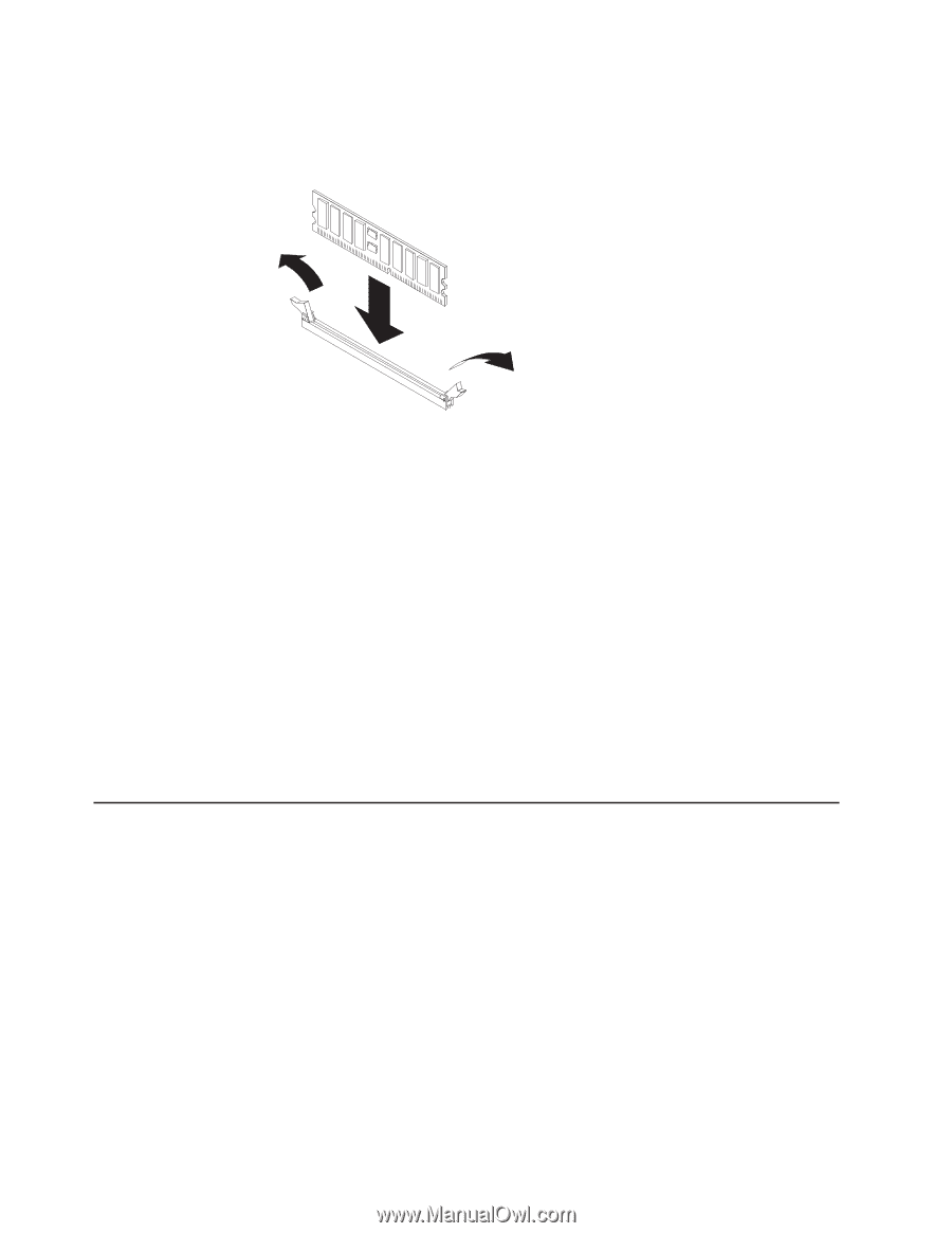
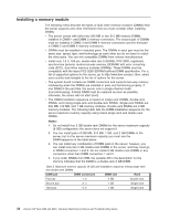
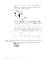
7. Install the DIMMs in the sequence shown in the notes at the beginning of this section. Attention: To avoid breaking the retaining clips or damaging the DIMM connectors, open and close the clips gently. a. Open the retaining clips and, if necessary, remove any existing DIMM. b. Touch the static-protective package containing the DIMM to any unpainted metal surface on the server. Then, remove the new DIMM from the package. c. Turn the DIMM so that the DIMM keys align correctly with the slot. d. Insert the DIMM into the connector, pressing gently but firmly until the retaining clips close. 8. Insert the DIMM into the connector by aligning the edges of the DIMM with the slots at the ends of the DIMM connector. Firmly press the DIMM straight down into the connector by applying pressure on both ends of the DIMM simultaneously. The retaining clips snap into the locked position when the DIMM is firmly seated in the connector. If there is a gap between the DIMM and the retaining clips, the DIMM has not been correctly installed. Open the retaining clips, remove the DIMM, and then reinsert it. 9. If you have other options to install or remove, do so now; otherwise, close the microprocessor air baffle (see "Opening and closing the microprocessor air baffle" on page 33), replace the support bracket (see "Removing and installing the support bracket" on page 32), and go to "Completing the installation" on page 60. Installing a drive Depending on the server model, one or more of the following drives might be installed in the server: v Diskette drive v Hard disk drive v CD-ROM drive 36 xSeries 226 Type 8488 and 8648: Hardware Maintenance Manual and Troubleshooting Guide
-
 1
1 -
2
-
3
-
4
-
5
-
6
-
7
-
8
-
9
-
10
-
11
-
12
-
13
-
14
-
15
-
16
-
17
-
18
-
19
-
20
-
21
-
22
-
23
-
24
-
25
-
26
-
27
-
28
-
29
-
30
-
31
-
32
-
33
-
34
-
35
-
36
-
37
-
38
-
39
-
40
-
 41
41 -
 42
42 -
 43
43 -
 44
44 -
 45
45 -
 46
46 -
 47
47 -
 48
48 -
 49
49 -
 50
50 -
 51
51 -
52
-
53
-
54
-
55
-
56
-
57
-
58
-
59
-
60
-
61
-
62
-
63
-
64
-
65
-
66
-
67
-
68
-
69
-
70
-
71
-
72
-
73
-
74
-
75
-
76
-
77
-
78
-
79
-
80
-
81
-
82
-
83
-
84
-
85
-
86
-
87
-
88
-
89
-
90
-
91
-
92
-
93
-
94
-
95
-
96
-
97
-
98
-
99
-
100
-
101
-
102
-
103
-
104
-
105
-
106
-
107
-
108
-
109
-
110
-
111
-
112
-
113
-
114
-
115
-
116
-
117
-
118
-
119
-
120
-
121
-
122
-
123
-
124
-
125
-
126
-
127
-
128
-
129
-
130
-
131
-
132
-
133
-
134
-
135
-
136
-
137
-
138
-
139
-
140
-
141
-
142
-
143
-
144
-
145
-
146
-
147
-
148
-
149
-
150
-
151
-
152
-
153
-
154
-
155
-
156
-
157
-
158
-
159
-
160
-
161
-
162
-
163
-
164
-
165
-
166
-
167
-
168
-
169
-
170
-
171
-
172
-
173
-
174
-
175
-
176
-
177
-
178
-
179
-
180
-
181
-
182
-
183
-
184
-
185
-
186
-
187
-
188
-
189
-
190
-
191
-
192
-
193
-
194
-
195
-
196
-
197
-
198
-
199
-
200
 |
 |