Dell PowerConnect Brocade M6505 Brocade 7.1.0 Web Tools Administrator's Guide - Page 155
Viewing the power supply status, Checking the physical health of a switch, Power, Logical Switch
 |
View all Dell PowerConnect Brocade M6505 manuals
Add to My Manuals
Save this manual to your list of manuals |
Page 155 highlights
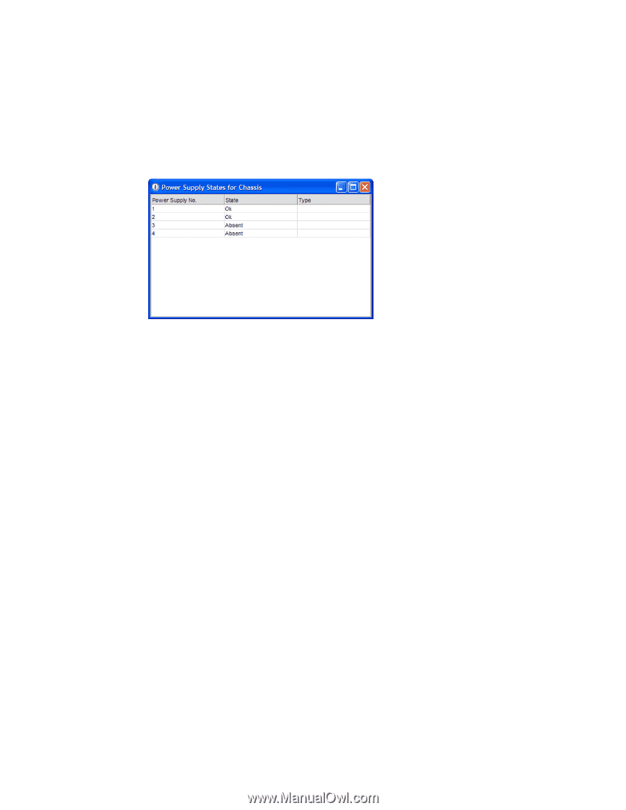
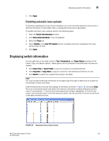
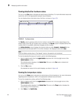
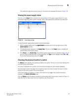
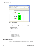
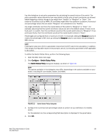
Displaying switch information 9 The detailed temperature sensor states for the switch are displayed, as shown in Figure 28. Viewing the power supply status The icon on the Power button indicates the overall status of the power supply status. For more information regarding switch power modules, refer to the appropriate hardware documentation. FIGURE 30 Power States window To view the power supply status, perform the following steps. 1. Select a logical switch from the Logical Switch drop-down list in the top-right corner of the Switch Explorer window. 2. The selected switch displays in the Switch View. The icon on the Power button indicates the overall status of the power supply. 3. Click Power on the Switch View. The detailed power supply states are displayed (Figure 30). If you are using the Brocade 6510 or Brocade 6520, the Type column displays either AC or DC. For all other hardware the value will be N/A. Checking the physical health of a switch The Status button displays the operational state of the switch. The icon on the button displays the real-time status of the switch. If no data is available from a switch, the most recent background color remains displayed. Any error-based status messages that is based on a per time interval cause the status to show faulty until the entire sample interval has passed. If the switch status is marginal or critical, information on the trigger that caused that status displays in the Switch Information view. Click the Status button to display a detailed, customizable switch status report, shown in Figure 31. Note that this is a static report and not a dynamic view of the switch. Web Tools Administrator's Guide 127 53-1002756-01
-
 1
1 -
2
-
3
-
4
-
5
-
6
-
7
-
8
-
9
-
10
-
11
-
12
-
13
-
14
-
15
-
16
-
17
-
18
-
19
-
20
-
21
-
22
-
23
-
24
-
25
-
26
-
27
-
28
-
29
-
30
-
31
-
32
-
33
-
34
-
35
-
36
-
37
-
38
-
39
-
40
-
41
-
42
-
43
-
44
-
45
-
46
-
47
-
48
-
49
-
50
-
51
-
52
-
53
-
54
-
55
-
56
-
57
-
58
-
59
-
60
-
61
-
62
-
63
-
64
-
65
-
66
-
67
-
68
-
69
-
70
-
71
-
72
-
73
-
74
-
75
-
76
-
77
-
78
-
79
-
80
-
81
-
82
-
83
-
84
-
85
-
86
-
87
-
88
-
89
-
90
-
91
-
92
-
93
-
94
-
95
-
96
-
97
-
98
-
99
-
100
-
101
-
102
-
103
-
104
-
105
-
106
-
107
-
108
-
109
-
110
-
111
-
112
-
113
-
114
-
115
-
116
-
117
-
118
-
119
-
120
-
121
-
122
-
123
-
124
-
125
-
126
-
127
-
128
-
129
-
130
-
131
-
132
-
133
-
134
-
135
-
136
-
137
-
138
-
139
-
140
-
141
-
142
-
143
-
144
-
145
-
146
-
147
-
148
-
149
-
 150
150 -
 151
151 -
 152
152 -
 153
153 -
 154
154 -
 155
155 -
 156
156 -
 157
157 -
 158
158 -
 159
159 -
 160
160 -
161
-
162
-
163
-
164
-
165
-
166
-
167
-
168
-
169
-
170
-
171
-
172
-
173
-
174
-
175
-
176
-
177
-
178
-
179
-
180
-
181
-
182
-
183
-
184
-
185
-
186
-
187
-
188
-
189
-
190
-
191
-
192
-
193
-
194
-
195
-
196
-
197
-
198
-
199
-
200
-
201
-
202
-
203
-
204
-
205
-
206
-
207
-
208
-
209
-
210
-
211
-
212
-
213
-
214
-
215
-
216
-
217
-
218
-
219
-
220
-
221
-
222
-
223
-
224
-
225
-
226
-
227
-
228
-
229
-
230
-
231
-
232
-
233
-
234
-
235
-
236
-
237
-
238
-
239
-
240
-
241
-
242
-
243
-
244
-
245
-
246
-
247
-
248
-
249
-
250
-
251
-
252
-
253
-
254
-
255
-
256
-
257
-
258
-
259
-
260
-
261
-
262
-
263
-
264
-
265
-
266
-
267
-
268
 |
 |