Dell PowerConnect Brocade M6505 Brocade 7.1.0 Web Tools Administrator's Guide - Page 247

Adding an LLDP profile, Type/Length/Value TLV.

Page 247 highlights

LLDP-DCBX configuration 17 Adding an LLDP profile The LLDP profile determines LLDP settings per port. To add an LLDP profile, perform the following steps. 1. Select the DCB tab on the Switch Administration window. 2. Select the LLDP-DCBX tab. 3. Select the LLDP Profile tab. 4. Click Add. The LLDP Configuration dialog box displays. 5. Enter a name for the configuration in the Name field. 6. Optionally, add a description in the Description field. 7. Select the Mode. For Mode, the choices are Tx (transmit), Rx, (receive) or Both. The default is Both. 8. In the Hello field, enter a time value in seconds. The Hello value sets the interval between hello bridge protocol data units sent by the root switch configuration messages. The range is 4 to 180 seconds. The default is the global configuration range. 9. In the Multiplier field, set the number of consecutive misses allowed before LLDP considers the interface to be down. The range is 2 to 10. The default is the global configuration range. The multiplier is related to the Hello time interval. Using the defaults, you wait four times (the multiplier value) at 30 second intervals (the hello value) before giving up on the interface. 10. Select the parameters you want to exchange. Note that the term TLV indicates packaging of parameters into a Brocade-specific Type/Length/Value (TLV). - Advertise Optional-tlv-Advertises the following optional TLVs: • system-description-Describes switch or blade characteristics. • port-description-Describes the configured port. • system-name-Specifies the system name. • system capabilities-Describes the system capabilities. Web Tools Administrator's Guide 219 53-1002756-01

  • 1
  • 2
  • 3
  • 4
  • 5
  • 6
  • 7
  • 8
  • 9
  • 10
  • 11
  • 12
  • 13
  • 14
  • 15
  • 16
  • 17
  • 18
  • 19
  • 20
  • 21
  • 22
  • 23
  • 24
  • 25
  • 26
  • 27
  • 28
  • 29
  • 30
  • 31
  • 32
  • 33
  • 34
  • 35
  • 36
  • 37
  • 38
  • 39
  • 40
  • 41
  • 42
  • 43
  • 44
  • 45
  • 46
  • 47
  • 48
  • 49
  • 50
  • 51
  • 52
  • 53
  • 54
  • 55
  • 56
  • 57
  • 58
  • 59
  • 60
  • 61
  • 62
  • 63
  • 64
  • 65
  • 66
  • 67
  • 68
  • 69
  • 70
  • 71
  • 72
  • 73
  • 74
  • 75
  • 76
  • 77
  • 78
  • 79
  • 80
  • 81
  • 82
  • 83
  • 84
  • 85
  • 86
  • 87
  • 88
  • 89
  • 90
  • 91
  • 92
  • 93
  • 94
  • 95
  • 96
  • 97
  • 98
  • 99
  • 100
  • 101
  • 102
  • 103
  • 104
  • 105
  • 106
  • 107
  • 108
  • 109
  • 110
  • 111
  • 112
  • 113
  • 114
  • 115
  • 116
  • 117
  • 118
  • 119
  • 120
  • 121
  • 122
  • 123
  • 124
  • 125
  • 126
  • 127
  • 128
  • 129
  • 130
  • 131
  • 132
  • 133
  • 134
  • 135
  • 136
  • 137
  • 138
  • 139
  • 140
  • 141
  • 142
  • 143
  • 144
  • 145
  • 146
  • 147
  • 148
  • 149
  • 150
  • 151
  • 152
  • 153
  • 154
  • 155
  • 156
  • 157
  • 158
  • 159
  • 160
  • 161
  • 162
  • 163
  • 164
  • 165
  • 166
  • 167
  • 168
  • 169
  • 170
  • 171
  • 172
  • 173
  • 174
  • 175
  • 176
  • 177
  • 178
  • 179
  • 180
  • 181
  • 182
  • 183
  • 184
  • 185
  • 186
  • 187
  • 188
  • 189
  • 190
  • 191
  • 192
  • 193
  • 194
  • 195
  • 196
  • 197
  • 198
  • 199
  • 200
  • 201
  • 202
  • 203
  • 204
  • 205
  • 206
  • 207
  • 208
  • 209
  • 210
  • 211
  • 212
  • 213
  • 214
  • 215
  • 216
  • 217
  • 218
  • 219
  • 220
  • 221
  • 222
  • 223
  • 224
  • 225
  • 226
  • 227
  • 228
  • 229
  • 230
  • 231
  • 232
  • 233
  • 234
  • 235
  • 236
  • 237
  • 238
  • 239
  • 240
  • 241
  • 242
  • 243
  • 244
  • 245
  • 246
  • 247
  • 248
  • 249
  • 250
  • 251
  • 252
  • 253
  • 254
  • 255
  • 256
  • 257
  • 258
  • 259
  • 260
  • 261
  • 262
  • 263
  • 264
  • 265
  • 266
  • 267
  • 268

Web Tools Administrator’s Guide
219
53-1002756-01
LLDP-DCBX configuration
17
Adding an LLDP profile
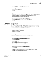
The LLDP profile determines LLDP settings per port.
To add an LLDP profile, perform the following steps.
1.
Select the
DCB tab
on the
Switch Administration
window.
2.
Select the
LLDP-DCBX
tab.
3.
Select the
LLDP Profile tab.
4.
Click
Add
.
The
LLDP Configuration
dialog box displays.
5.
Enter a name for the configuration in the
Name
field.
6.
Optionally, add a description in the
Description
field.
7.
Select the
Mode
.
For
Mode
, the choices are
Tx
(transmit),
Rx
, (receive) or
Both
. The default is
Both
.
8.
In the
Hello
field, enter a time value in seconds.
The Hello value sets the interval between hello bridge protocol data units sent by the root
switch configuration messages. The range is 4 to 180 seconds. The default is the global
configuration range.
9.
In the
Multiplier
field, set the number of consecutive misses allowed before LLDP considers
the interface to be down.
The range is 2 to 10. The default is the global configuration range. The multiplier
is related to
the Hello time interval. Using the defaults, you wait four times (the multiplier value) at 30
second intervals (the hello value) before giving up on the interface.
10.
Select the parameters you want to exchange.
Note that the term TLV indicates packaging of parameters into a Brocade-specific
Type/Length/Value (TLV).
-
Advertise Optional-tlv
—Advertises the following optional TLVs:
system-description
—Describes switch or blade characteristics.
port-description
—Describes the configured port.
system-name
—Specifies the system name.
system capabilities
—Describes the system capabilities.