Dell PowerConnect Brocade M6505 Brocade 7.1.0 Web Tools Administrator's Guide - Page 244
Editing the DCB map, Adding a traffic class map, Priority Flow Control Status
 |
View all Dell PowerConnect Brocade M6505 manuals
Add to My Manuals
Save this manual to your list of manuals |
Page 244 highlights
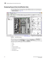
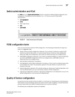
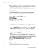
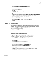
17 Quality of Service configuration • You can edit the DCB map. The DCB map defines priority and priority group tables that support Enhanced Transmission Selection (ETS). ETS allows allocation of bandwidth to different traffic classes. DCB maps also allow you to enable Priority Flow Control (PFC). • You can create a traffic class map. A traffic class map can be used to map a specific class of traffic to a specific Class of Service (CoS). Editing the DCB map The DCB map defines priority and priority group tables that support Enhanced Transmission Selection (ETS). ETS allows bandwidth to be allocated based on priority settings through an exchange of priority group tables. To edit the DCB map, perform the following steps. 1. Select the DCB tab on the Switch Administration window. 2. Select the QoS tab. 3. Select the DCB Map tab. 4. Select the default DCB map, and click Edit. The DCB Map Configuration dialog box displays. 5. Enter a precedence value in the Precedence field. The value is specified as a number. The allowable range is 1 to 100. The default is 1. The precedence value controls QoS scheduling policies. The scheduler gives precedence to the highest precedence value. When the DCB Map Configuration dialog box displays, the default values shown in the Priority Group Map match the IEEE 802.1Q recommendation for systems supporting eight traffic classes. The Priority Group Map displays the Layer 2 Cos values mapped to Priority Group ID (PGID). PGID values are in the form .. A policy value of 15 indicates Priority values run from 0 (highest priority) to 7 (lowest priority). Note that this is contrary to the CoS values, which run from 7 (highest priority) to 0 (lowest priority). 6. Create a new priority group by clicking Add next to the Priority Group table. An entry is added to the Priority Group table. NOTE When you add an entry, a PGID is automatically assigned. The PGID is an integer from 0 to 7. The first added entry is given a PGID of 0, and the PGID increments by one for each additional added entry until a PGID of 7 is reached. 7. Edit the Bandwidth entry to indicate the desired percentage of total bandwidth. 8. Change the Priority Flow Control Status to Enabled to enable PFC for the entry. 9. Click OK. The new priority group displays in the Priority Group Map. Adding a traffic class map CoS priorities can be mapped to traffic classes using a traffic class map. 216 Web Tools Administrator's Guide 53-1002756-01
-
 1
1 -
2
-
3
-
4
-
5
-
6
-
7
-
8
-
9
-
10
-
11
-
12
-
13
-
14
-
15
-
16
-
17
-
18
-
19
-
20
-
21
-
22
-
23
-
24
-
25
-
26
-
27
-
28
-
29
-
30
-
31
-
32
-
33
-
34
-
35
-
36
-
37
-
38
-
39
-
40
-
41
-
42
-
43
-
44
-
45
-
46
-
47
-
48
-
49
-
50
-
51
-
52
-
53
-
54
-
55
-
56
-
57
-
58
-
59
-
60
-
61
-
62
-
63
-
64
-
65
-
66
-
67
-
68
-
69
-
70
-
71
-
72
-
73
-
74
-
75
-
76
-
77
-
78
-
79
-
80
-
81
-
82
-
83
-
84
-
85
-
86
-
87
-
88
-
89
-
90
-
91
-
92
-
93
-
94
-
95
-
96
-
97
-
98
-
99
-
100
-
101
-
102
-
103
-
104
-
105
-
106
-
107
-
108
-
109
-
110
-
111
-
112
-
113
-
114
-
115
-
116
-
117
-
118
-
119
-
120
-
121
-
122
-
123
-
124
-
125
-
126
-
127
-
128
-
129
-
130
-
131
-
132
-
133
-
134
-
135
-
136
-
137
-
138
-
139
-
140
-
141
-
142
-
143
-
144
-
145
-
146
-
147
-
148
-
149
-
150
-
151
-
152
-
153
-
154
-
155
-
156
-
157
-
158
-
159
-
160
-
161
-
162
-
163
-
164
-
165
-
166
-
167
-
168
-
169
-
170
-
171
-
172
-
173
-
174
-
175
-
176
-
177
-
178
-
179
-
180
-
181
-
182
-
183
-
184
-
185
-
186
-
187
-
188
-
189
-
190
-
191
-
192
-
193
-
194
-
195
-
196
-
197
-
198
-
199
-
200
-
201
-
202
-
203
-
204
-
205
-
206
-
207
-
208
-
209
-
210
-
211
-
212
-
213
-
214
-
215
-
216
-
217
-
218
-
219
-
220
-
221
-
222
-
223
-
224
-
225
-
226
-
227
-
228
-
229
-
230
-
231
-
232
-
233
-
234
-
235
-
236
-
237
-
238
-
 239
239 -
 240
240 -
 241
241 -
 242
242 -
 243
243 -
 244
244 -
 245
245 -
 246
246 -
 247
247 -
 248
248 -
 249
249 -
250
-
251
-
252
-
253
-
254
-
255
-
256
-
257
-
258
-
259
-
260
-
261
-
262
-
263
-
264
-
265
-
266
-
267
-
268
 |
 |