Dell PowerConnect Brocade M6505 Brocade 7.1.0 Web Tools Administrator's Guide - Page 235
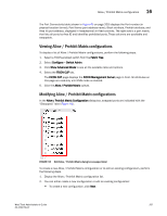
Viewing Allow / Prohibit Matrix configurations, Fabric Tree, Con Switch Admin
 |
View all Dell PowerConnect Brocade M6505 manuals
Add to My Manuals
Save this manual to your list of manuals |
Page 235 highlights
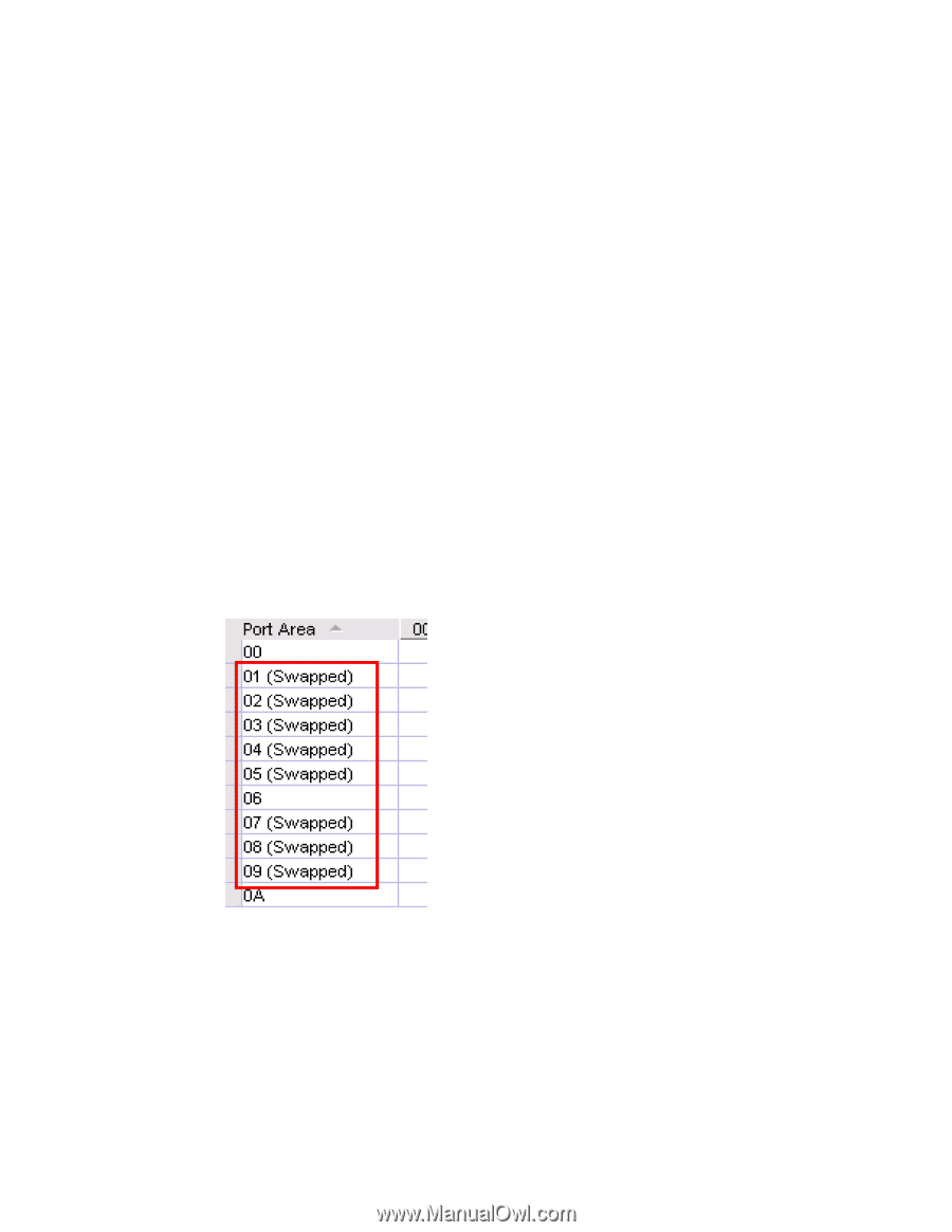
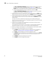
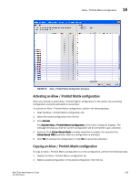
Allow / Prohibit Matrix configuration 16 The Port Connectivity table (shown in Figure 45 on page 209) displays the Port number (in physical-location format), Port Name (port address name), Block attribute, Prohibit attribute, and Area Id (port address, displayed in hexadecimal) in fixed columns. The right side is a port matrix, that lists all ports by Area ID and identifies prohibited ports. Those columns are scrollable and swappable. Viewing Allow / Prohibit Matrix configurations To display a list of Allow / Prohibit Matrix configurations, perform the following steps. 1. Select a FICON-enabled switch from the Fabric Tree. 2. Select Configure > Switch Admin. 3. Click Show Advanced Mode to see all the available tabs and options. 4. Select the FICON CUP tab. The FICON CUP page displays the FICON Management Server page in front. All attributes on this page are read-only until FMS mode is enabled. 5. Click the Allow / Prohibit Matrix subtab. Modifying Allow / Prohibit Matrix configurations In the Allow / Prohibit Matrix Configuration dialog box, swapped ports are indicated with the "(Swapped)" label (Figure 44). FIGURE 44 Edit Allow / Prohibit Matrix dialog box swapped label To create a new Allow / Prohibit Matrix configuration or to edit an existing configuration, perform the following steps. 1. Display the Allow / Prohibit Matrix configuration list. 2. You can either create a new configuration or edit an existing configuration: • To create a new configuration, click New. Web Tools Administrator's Guide 207 53-1002756-01
-
 1
1 -
2
-
3
-
4
-
5
-
6
-
7
-
8
-
9
-
10
-
11
-
12
-
13
-
14
-
15
-
16
-
17
-
18
-
19
-
20
-
21
-
22
-
23
-
24
-
25
-
26
-
27
-
28
-
29
-
30
-
31
-
32
-
33
-
34
-
35
-
36
-
37
-
38
-
39
-
40
-
41
-
42
-
43
-
44
-
45
-
46
-
47
-
48
-
49
-
50
-
51
-
52
-
53
-
54
-
55
-
56
-
57
-
58
-
59
-
60
-
61
-
62
-
63
-
64
-
65
-
66
-
67
-
68
-
69
-
70
-
71
-
72
-
73
-
74
-
75
-
76
-
77
-
78
-
79
-
80
-
81
-
82
-
83
-
84
-
85
-
86
-
87
-
88
-
89
-
90
-
91
-
92
-
93
-
94
-
95
-
96
-
97
-
98
-
99
-
100
-
101
-
102
-
103
-
104
-
105
-
106
-
107
-
108
-
109
-
110
-
111
-
112
-
113
-
114
-
115
-
116
-
117
-
118
-
119
-
120
-
121
-
122
-
123
-
124
-
125
-
126
-
127
-
128
-
129
-
130
-
131
-
132
-
133
-
134
-
135
-
136
-
137
-
138
-
139
-
140
-
141
-
142
-
143
-
144
-
145
-
146
-
147
-
148
-
149
-
150
-
151
-
152
-
153
-
154
-
155
-
156
-
157
-
158
-
159
-
160
-
161
-
162
-
163
-
164
-
165
-
166
-
167
-
168
-
169
-
170
-
171
-
172
-
173
-
174
-
175
-
176
-
177
-
178
-
179
-
180
-
181
-
182
-
183
-
184
-
185
-
186
-
187
-
188
-
189
-
190
-
191
-
192
-
193
-
194
-
195
-
196
-
197
-
198
-
199
-
200
-
201
-
202
-
203
-
204
-
205
-
206
-
207
-
208
-
209
-
210
-
211
-
212
-
213
-
214
-
215
-
216
-
217
-
218
-
219
-
220
-
221
-
222
-
223
-
224
-
225
-
226
-
227
-
228
-
229
-
 230
230 -
 231
231 -
 232
232 -
 233
233 -
 234
234 -
 235
235 -
 236
236 -
 237
237 -
 238
238 -
 239
239 -
 240
240 -
241
-
242
-
243
-
244
-
245
-
246
-
247
-
248
-
249
-
250
-
251
-
252
-
253
-
254
-
255
-
256
-
257
-
258
-
259
-
260
-
261
-
262
-
263
-
264
-
265
-
266
-
267
-
268
 |
 |