Dell PowerEdge M710 Web Tools Administrator’s Guide - Page 173
Defining Switch Policy
 |
View all Dell PowerEdge M710 manuals
Add to My Manuals
Save this manual to your list of manuals |
Page 173 highlights
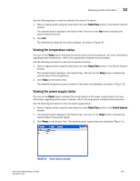
DRAFT: BROCADE CONFIDENTIAL Defining Switch Policy 10 NOTE The Port Detail Report and Switch Availability Monitor (SAM) reports display the details of only those ports which are members of the current Admin Domain context and the E_Ports of the switch. 4. Optional: Hold the cursor on the Action bar and click an action to perform one of the following options: • Refresh the information displayed in the report • Customize the report • View the data in raw XML format • View the style sheet for the report • View the XML schema for the report Defining Switch Policy The Switch Policy dialog box lets you define the values for what you consider a healthy switch. The parameters for Switch Policy define whether the unit is listed as being "Healthy", "Marginal", or "Down". Use this dialog box to set policy parameters for calculating the overall status of the switch. The policy parameter values determine how many failed or faulty units of each contributor are allowed before triggering a status change in the switch from "Healthy" to "Marginal" or "Down". The existence of policies such as WWN, CP, and Blade might differ from platform to platform. Any single contributor can force the overall status of the switch to MARGINAL or DOWN. For example, assuming that the switch contributor values are set to the default values, if there is one faulty port in a switch, then this contributor would set the overall switch status to MARGINAL. If two ports were faulty, then this contributor would set the overall switch status to DOWN. Note that the value, 0, for a parameter, means that it is NOT used in the calculation. In addition, if the range of configurable values in the prompt is (0..0), the policy parameter is NOT applicable to the switch. Use the following procedure to define the Switch Status Policy. 1. Open the Web Tools main page. 2. Click the Switch Status Policy button. The Switch Status Policy dialog box displays, as shown in Figure 43. Web Tools Administrator's Guide 145 53-1001772-01
-
 1
1 -
2
-
3
-
4
-
5
-
6
-
7
-
8
-
9
-
10
-
11
-
12
-
13
-
14
-
15
-
16
-
17
-
18
-
19
-
20
-
21
-
22
-
23
-
24
-
25
-
26
-
27
-
28
-
29
-
30
-
31
-
32
-
33
-
34
-
35
-
36
-
37
-
38
-
39
-
40
-
41
-
42
-
43
-
44
-
45
-
46
-
47
-
48
-
49
-
50
-
51
-
52
-
53
-
54
-
55
-
56
-
57
-
58
-
59
-
60
-
61
-
62
-
63
-
64
-
65
-
66
-
67
-
68
-
69
-
70
-
71
-
72
-
73
-
74
-
75
-
76
-
77
-
78
-
79
-
80
-
81
-
82
-
83
-
84
-
85
-
86
-
87
-
88
-
89
-
90
-
91
-
92
-
93
-
94
-
95
-
96
-
97
-
98
-
99
-
100
-
101
-
102
-
103
-
104
-
105
-
106
-
107
-
108
-
109
-
110
-
111
-
112
-
113
-
114
-
115
-
116
-
117
-
118
-
119
-
120
-
121
-
122
-
123
-
124
-
125
-
126
-
127
-
128
-
129
-
130
-
131
-
132
-
133
-
134
-
135
-
136
-
137
-
138
-
139
-
140
-
141
-
142
-
143
-
144
-
145
-
146
-
147
-
148
-
149
-
150
-
151
-
152
-
153
-
154
-
155
-
156
-
157
-
158
-
159
-
160
-
161
-
162
-
163
-
164
-
165
-
166
-
167
-
 168
168 -
 169
169 -
 170
170 -
 171
171 -
 172
172 -
 173
173 -
 174
174 -
 175
175 -
 176
176 -
 177
177 -
 178
178 -
179
-
180
-
181
-
182
-
183
-
184
-
185
-
186
-
187
-
188
-
189
-
190
-
191
-
192
-
193
-
194
-
195
-
196
-
197
-
198
-
199
-
200
-
201
-
202
-
203
-
204
-
205
-
206
-
207
-
208
-
209
-
210
-
211
-
212
-
213
-
214
-
215
-
216
-
217
-
218
-
219
-
220
-
221
-
222
-
223
-
224
-
225
-
226
-
227
-
228
-
229
-
230
-
231
-
232
-
233
-
234
-
235
-
236
-
237
-
238
-
239
-
240
-
241
-
242
-
243
-
244
-
245
-
246
-
247
-
248
-
249
-
250
-
251
-
252
-
253
-
254
-
255
-
256
-
257
-
258
-
259
-
260
-
261
-
262
-
263
-
264
-
265
-
266
-
267
-
268
-
269
-
270
-
271
-
272
-
273
-
274
-
275
-
276
-
277
-
278
-
279
-
280
-
281
-
282
-
283
-
284
-
285
-
286
-
287
-
288
-
289
-
290
-
291
-
292
-
293
-
294
-
295
-
296
-
297
-
298
-
299
-
300
-
301
-
302
-
303
-
304
-
305
-
306
-
307
-
308
-
309
-
310
 |
 |
