Dell PowerEdge M710 Web Tools Administrator’s Guide - Page 87
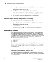
Viewing logical ports, Virtual Fabrics overview
 |
View all Dell PowerEdge M710 manuals
Add to My Manuals
Save this manual to your list of manuals |
Page 87 highlights
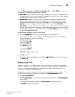
DRAFT: BROCADE CONFIDENTIAL Virtual Fabrics overview 3 Under the Switch Information tab, Base Switch, Default Switch, and Allow XISL Use are specific to VIrtual Fabrics. These options perform these functions: • Base Switch indicates whether or not the logical switch can act as a base switch. A base switch is a special logical switch that can be used for chassis interconnection. Each chassis may only designate only one logical switch as a base switch. • Default Switch indicates whether or not the logical switch is the default logical switch. The default logical switch is equivalent to the normal, discovered physical switch topology. It is automatically assigned fabric ID 128. If you do not log in to a specific logical switch using Options on the login dialog box, the default logical switch displays in the Switch View. • Allow XISL Use indicates whether or not the logical switch is allowed to connect to other logical switches using an extended inter-switch link (XISL). Base switches may use XISLs. Dynamically created logical switches can use the XISL for traffic, only if Allow XISL Use is enabled through CLI using the configure command. Use the following procedure to select a logical switch. 1. Use the Logical Switch selector to select the fabric ID, as shown in Figure 19. You must have the EGM license installed to view the Logical Switch selection. A dialog box displays asking you to confirm your selection. FIGURE 19 Logical switch selector 2. Click Yes to confirm. The selected logical switch displays. Note that the Logical Switch selector is relocated above the Switch View. Viewing logical ports When base switches are connected through XISLs, a base fabric is formed that includes logical switches in different chassis. A logical link is formed dynamically among logical switches that have the same FID to carry frames between the logical switches. Logical ports are created in the respective switches to support the logical link. Logical ports are software constructs, and have no corresponding hardware to represent them on the Switch View. Logical port information is available in the Port Administration window. 1. Select Port Administration. The Port Administration window displays. Logical ports are displayed in the FC Ports Explorer tree structure. 2. To view logical port properties, expand the Logical Ports folder, and select a port. The General properties are displayed. Web Tools Administrator's Guide 59 53-1001772-01
-
 1
1 -
2
-
3
-
4
-
5
-
6
-
7
-
8
-
9
-
10
-
11
-
12
-
13
-
14
-
15
-
16
-
17
-
18
-
19
-
20
-
21
-
22
-
23
-
24
-
25
-
26
-
27
-
28
-
29
-
30
-
31
-
32
-
33
-
34
-
35
-
36
-
37
-
38
-
39
-
40
-
41
-
42
-
43
-
44
-
45
-
46
-
47
-
48
-
49
-
50
-
51
-
52
-
53
-
54
-
55
-
56
-
57
-
58
-
59
-
60
-
61
-
62
-
63
-
64
-
65
-
66
-
67
-
68
-
69
-
70
-
71
-
72
-
73
-
74
-
75
-
76
-
77
-
78
-
79
-
80
-
81
-
 82
82 -
 83
83 -
 84
84 -
 85
85 -
 86
86 -
 87
87 -
 88
88 -
 89
89 -
 90
90 -
 91
91 -
 92
92 -
93
-
94
-
95
-
96
-
97
-
98
-
99
-
100
-
101
-
102
-
103
-
104
-
105
-
106
-
107
-
108
-
109
-
110
-
111
-
112
-
113
-
114
-
115
-
116
-
117
-
118
-
119
-
120
-
121
-
122
-
123
-
124
-
125
-
126
-
127
-
128
-
129
-
130
-
131
-
132
-
133
-
134
-
135
-
136
-
137
-
138
-
139
-
140
-
141
-
142
-
143
-
144
-
145
-
146
-
147
-
148
-
149
-
150
-
151
-
152
-
153
-
154
-
155
-
156
-
157
-
158
-
159
-
160
-
161
-
162
-
163
-
164
-
165
-
166
-
167
-
168
-
169
-
170
-
171
-
172
-
173
-
174
-
175
-
176
-
177
-
178
-
179
-
180
-
181
-
182
-
183
-
184
-
185
-
186
-
187
-
188
-
189
-
190
-
191
-
192
-
193
-
194
-
195
-
196
-
197
-
198
-
199
-
200
-
201
-
202
-
203
-
204
-
205
-
206
-
207
-
208
-
209
-
210
-
211
-
212
-
213
-
214
-
215
-
216
-
217
-
218
-
219
-
220
-
221
-
222
-
223
-
224
-
225
-
226
-
227
-
228
-
229
-
230
-
231
-
232
-
233
-
234
-
235
-
236
-
237
-
238
-
239
-
240
-
241
-
242
-
243
-
244
-
245
-
246
-
247
-
248
-
249
-
250
-
251
-
252
-
253
-
254
-
255
-
256
-
257
-
258
-
259
-
260
-
261
-
262
-
263
-
264
-
265
-
266
-
267
-
268
-
269
-
270
-
271
-
272
-
273
-
274
-
275
-
276
-
277
-
278
-
279
-
280
-
281
-
282
-
283
-
284
-
285
-
286
-
287
-
288
-
289
-
290
-
291
-
292
-
293
-
294
-
295
-
296
-
297
-
298
-
299
-
300
-
301
-
302
-
303
-
304
-
305
-
306
-
307
-
308
-
309
-
310
 |
 |
