Epson SureColor S50670 User Manual - Page 11
Waste ink bottle, Waste ink bottle holder
 |
View all Epson SureColor S50670 manuals
Add to My Manuals
Save this manual to your list of manuals |
Page 11 highlights
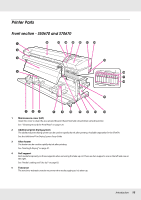
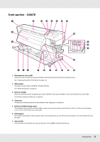
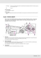
6 Roll core holder locking screw The locking screws keep the roll core holders in place once they have been attached to the roll core. There are two lift levers: one on the left and one on the right. 7 Roll support Place the used roll core for media take-up on these holders. There are two supports: one on the left and one on the right. 8 Auto switch Use this switch to select the auto take-up direction. Choose Off to disable auto take-up. 9 Manual switch Use this switch to select the manual take-up direction.AutoThe selected option takes effect when the Auto switch is in the Off position. 10 Casters There are two casters on each leg. Once installation is complete, the front casters should be kept locked while the printer is in use. 11 Airflow vents These vents vent air from inside the printer. Do not obstruct these vents. 12 Waste ink bottle holder Place the waste ink bottle in this holder. 13 Adjuster The adjusters keep the printer in place. After installing the printer, keep it securely in place during use. 14 Waste ink bottle Waste ink collects in this bottle. Replace with a new waste ink bottle when the level approaches the line. 15 Waste ink tube Waste ink is discharged from this tube. Be sure the end of this tube is in the waste ink bottle while the printer is in use. 16 Ink cartridge/replacement cartridge The number of each type of cartridge installed varies with the option selected for color mode. S70670: 8 colors/10 colors S50670: 4 colors/5 colors In 8 or 4 color mode, you need to use "replacement cartridges" to fill all slots. These are included with your printer. 17 Lock levers Raise the levers to unlock the ink cartridges prior to removal. Lower the levers to lock the cartridges in place after insertion. 18 Cartridge check lamp This lamp lights when an ink cartridge error occurs. On : An error occurred. Check the contents of the error on the control panel's screen. Off : No error. 19 AC inlet #1/AC inlet #2 Connects the power cable. Be sure to connect both cables. 20 LAN port See "LAN port" on page 19. Introduction 11
-
 1
1 -
2
-
3
-
4
-
5
-
 6
6 -
 7
7 -
 8
8 -
 9
9 -
 10
10 -
 11
11 -
 12
12 -
 13
13 -
 14
14 -
 15
15 -
 16
16 -
17
-
18
-
19
-
20
-
21
-
22
-
23
-
24
-
25
-
26
-
27
-
28
-
29
-
30
-
31
-
32
-
33
-
34
-
35
-
36
-
37
-
38
-
39
-
40
-
41
-
42
-
43
-
44
-
45
-
46
-
47
-
48
-
49
-
50
-
51
-
52
-
53
-
54
-
55
-
56
-
57
-
58
-
59
-
60
-
61
-
62
-
63
-
64
-
65
-
66
-
67
-
68
-
69
-
70
-
71
-
72
-
73
-
74
-
75
-
76
-
77
-
78
-
79
-
80
-
81
-
82
-
83
-
84
-
85
-
86
-
87
-
88
-
89
-
90
-
91
-
92
-
93
-
94
-
95
-
96
-
97
-
98
-
99
-
100
-
101
-
102
-
103
-
104
-
105
-
106
-
107
-
108
-
109
-
110
-
111
-
112
-
113
-
114
-
115
-
116
-
117
-
118
-
119
-
120
-
121
-
122
-
123
-
124
-
125
-
126
-
127
-
128
-
129
-
130
-
131
-
132
-
133
-
134
-
135
-
136
-
137
-
138
-
139
-
140
-
141
-
142
-
143
-
144
-
145
-
146
-
147
-
148
-
149
-
150
-
151
-
152
-
153
-
154
-
155
-
156
-
157
-
158
-
159
-
160
-
161
-
162
-
163
-
164
-
165
-
166
-
167
-
168
-
169
-
170
-
171
-
172
-
173
-
174
-
175
-
176
-
177
-
178
-
179
-
180
-
181
-
182
-
183
-
184
-
185
-
186
-
187
-
188
-
189
-
190
-
191
-
192
 |
 |