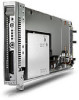
HP BladeSystem bc2800 Embedded Web System User Guide for the HP BladeSystem PC - Page 113
Configuring Spanning Tree - blade pc support
 |
View all HP BladeSystem bc2800 manuals
Add to My Manuals
Save this manual to your list of manuals |
Page 113 highlights
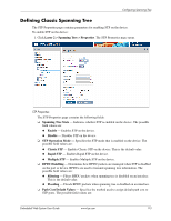
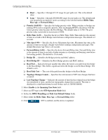
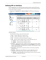
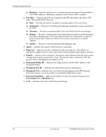
9 Configuring Spanning Tree Spanning Tree Protocol (STP) provides tree topography for any arrangement of bridges. STP also provides a single path between end stations on a network, eliminating loops. Loops occur when alternate routes exist between hosts. Loops in an extended network can cause bridges to forward traffic indefinitely, resulting in increased traffic and reducing network efficiency. Enabled by default, the Switch provides an MSTP-to-RSTP conversion parameter for configuring limited PVST/PVST+ Interoperability called MSTP-to-RSTP Conversion. When this feature is enabled, the switch retransmits only BPDUs on the VLAN from which they were received. Initial egress BPDUs transmit only on the VLAN to which the port is assigned. This option enables the HP Blade PC Switch to simulate multiple STP/RSTP bridges (VLAN unaware bridges), where the remote switch is communicating with either STP or RSTP. When using this feature, each port only reports the STP/RSTP bridge for its VLAN and internal MST Instance using standard IEEE STP/RSTP packets. Since each bridge is connected by at least one port to the spanning tree, at least one port for each VLAN will be in the forwarding state. MSTP-to-RSTP conversion is a global parameter, which applies to all ports that have Spanning Tree enabled. When enabled, neither switch port mode trunk or general can be enabled. An error message will be displayed if you attempt to change an interface switch port mode to either trunk or general. If more than two VLANs are required, the four primary uplinks can be used individually as access ports, but at the expense of loosing layer 2 redundancy. If more than two VLANs and redundancy are required, this feature must be disabled. HP recommends using IEEE 802.1s Multiple Spanning Trees for situations where high speed L2 redundancy and support for more than two VLANs is needed. The default configuration for this feature is as follows: ■ MSTP enabled by default ■ VLAN 1 mapped to MST instance 1 ■ MSTP-to-RSTP conversion enabled ■ VLAN 2 mapped to MST instance 2 ■ VLAN 3-4093 mapped to MST instance 15 The device supports the following STP versions: ■ Classic STP - Provides a single path between end stations, avoiding and eliminating loops. For more information on configuring Classic STP, see "Defining Classic Spanning Tree" on page 3. ■ Rapid STP - Detects and uses network topologies that provide faster convergence of the spanning tree, without creating forwarding loops. For more information on configuring Rapid STP, see "Defining Rapid Spanning Tree" on page 8. ■ Multiple STP - Provides various load balancing scenarios. For example, if port A is blocked in one STP instance, the same port can be placed in the Forwarding State in another STP instance. For more information on configuring Multiple STP, see "Defining Multiple Spanning Tree" on page 10. Embedded Web System User Guide www.hp.com 9-1
-
 1
1 -
2
-
3
-
4
-
5
-
6
-
7
-
8
-
9
-
10
-
11
-
12
-
13
-
14
-
15
-
16
-
17
-
18
-
19
-
20
-
21
-
22
-
23
-
24
-
25
-
26
-
27
-
28
-
29
-
30
-
31
-
32
-
33
-
34
-
35
-
36
-
37
-
38
-
39
-
40
-
41
-
42
-
43
-
44
-
45
-
46
-
47
-
48
-
49
-
50
-
51
-
52
-
53
-
54
-
55
-
56
-
57
-
58
-
59
-
60
-
61
-
62
-
63
-
64
-
65
-
66
-
67
-
68
-
69
-
70
-
71
-
72
-
73
-
74
-
75
-
76
-
77
-
78
-
79
-
80
-
81
-
82
-
83
-
84
-
85
-
86
-
87
-
88
-
89
-
90
-
91
-
92
-
93
-
94
-
95
-
96
-
97
-
98
-
99
-
100
-
101
-
102
-
103
-
104
-
105
-
106
-
107
-
 108
108 -
 109
109 -
 110
110 -
 111
111 -
 112
112 -
 113
113 -
 114
114 -
 115
115 -
 116
116 -
 117
117 -
 118
118 -
119
-
120
-
121
-
122
-
123
-
124
-
125
-
126
-
127
-
128
-
129
-
130
-
131
-
132
-
133
-
134
-
135
-
136
-
137
-
138
-
139
-
140
-
141
-
142
-
143
-
144
-
145
-
146
-
147
-
148
-
149
-
150
-
151
-
152
-
153
-
154
-
155
-
156
-
157
-
158
-
159
-
160
-
161
-
162
-
163
-
164
-
165
-
166
-
167
-
168
-
169
-
170
-
171
-
172
-
173
-
174
-
175
-
176
-
177
-
178
-
179
-
180
-
181
-
182
-
183
-
184
-
185
-
186
-
187
-
188
-
189
-
190
-
191
-
192
-
193
-
194
-
195
-
196
-
197
-
198
-
199
-
200
-
201
-
202
-
203
-
204
-
205
-
206
-
207
-
208
-
209
-
210
-
211
-
212
-
213
-
214
-
215
-
216
 |
 |