HP BladeSystem bc2800 Embedded Web System User Guide for the HP BladeSystem PC - Page 117
Defining STP on Interfaces
 |
View all HP BladeSystem bc2800 manuals
Add to My Manuals
Save this manual to your list of manuals |
Page 117 highlights
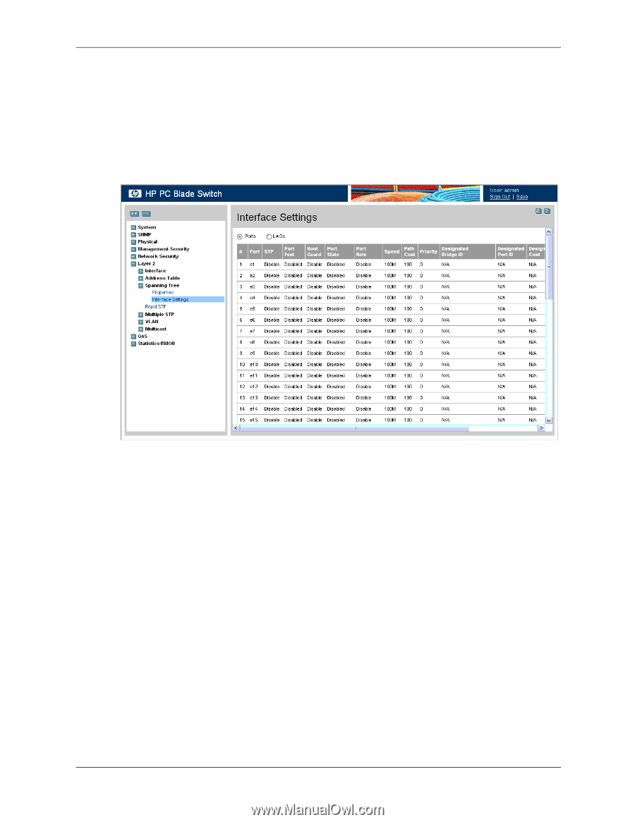
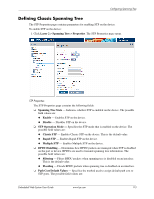
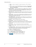
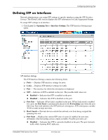
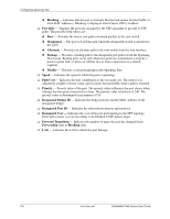
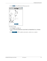
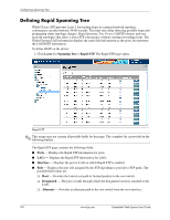
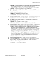
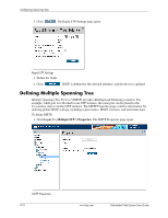
Configuring Spanning Tree Defining STP on Interfaces Network administrators can assign STP settings to specific interfaces using the STP Interface Settings. The Global LAGs section displays the STP information for Link Aggregated Groups. To assign STP settings to an interface: 1. Click Layer 2 > Spanning Tree > Interface Settings. The STP Interface Settings page opens: STP Interface Settings The STP Interface Settings contains the following fields: ❏ Ports - Displays STP interface settings for ports. ❏ LAGs - Displays STP interface settings for LAGs. ❏ Port - The interface for which the information is displayed. ❏ STP - Indicates if STP is enabled on the port. The possible field values are: ◆ Enabled - Indicates that STP is enabled on the port. ◆ Disabled - Indicates that STP is disabled on the port. ❏ Port Fast - Indicates if Fast Link is enabled on the port. If Fast Link mode is enabled for a port, the Port State is automatically placed in the Forwarding state when the port link is up. Fast Link optimizes the STP protocol convergence. STP convergence can take 30-60 seconds in large networks. ❏ Root Guard - Prevents devices outside the network core from being assigned the spanning tree root. ❏ Port State - Displays the current STP state of a port. If enabled, the port state determines what forwarding action is taken on traffic. Possible port states are: ◆ Disabled - Indicates that STP is currently disabled on the port. The port forwards traffic while learning MAC addresses. Embedded Web System User Guide www.hp.com 9-5
-
 1
1 -
2
-
3
-
4
-
5
-
6
-
7
-
8
-
9
-
10
-
11
-
12
-
13
-
14
-
15
-
16
-
17
-
18
-
19
-
20
-
21
-
22
-
23
-
24
-
25
-
26
-
27
-
28
-
29
-
30
-
31
-
32
-
33
-
34
-
35
-
36
-
37
-
38
-
39
-
40
-
41
-
42
-
43
-
44
-
45
-
46
-
47
-
48
-
49
-
50
-
51
-
52
-
53
-
54
-
55
-
56
-
57
-
58
-
59
-
60
-
61
-
62
-
63
-
64
-
65
-
66
-
67
-
68
-
69
-
70
-
71
-
72
-
73
-
74
-
75
-
76
-
77
-
78
-
79
-
80
-
81
-
82
-
83
-
84
-
85
-
86
-
87
-
88
-
89
-
90
-
91
-
92
-
93
-
94
-
95
-
96
-
97
-
98
-
99
-
100
-
101
-
102
-
103
-
104
-
105
-
106
-
107
-
108
-
109
-
110
-
111
-
 112
112 -
 113
113 -
 114
114 -
 115
115 -
 116
116 -
 117
117 -
 118
118 -
 119
119 -
 120
120 -
 121
121 -
 122
122 -
123
-
124
-
125
-
126
-
127
-
128
-
129
-
130
-
131
-
132
-
133
-
134
-
135
-
136
-
137
-
138
-
139
-
140
-
141
-
142
-
143
-
144
-
145
-
146
-
147
-
148
-
149
-
150
-
151
-
152
-
153
-
154
-
155
-
156
-
157
-
158
-
159
-
160
-
161
-
162
-
163
-
164
-
165
-
166
-
167
-
168
-
169
-
170
-
171
-
172
-
173
-
174
-
175
-
176
-
177
-
178
-
179
-
180
-
181
-
182
-
183
-
184
-
185
-
186
-
187
-
188
-
189
-
190
-
191
-
192
-
193
-
194
-
195
-
196
-
197
-
198
-
199
-
200
-
201
-
202
-
203
-
204
-
205
-
206
-
207
-
208
-
209
-
210
-
211
-
212
-
213
-
214
-
215
-
216
 |
 |