HP BladeSystem bc2800 Embedded Web System User Guide for the HP BladeSystem PC - Page 88
Configuring VLANs
 |
View all HP BladeSystem bc2800 manuals
Add to My Manuals
Save this manual to your list of manuals |
Page 88 highlights
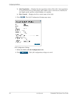
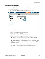
Configuring Interfaces 2. Click . The LACP Parameters Settings page opens: LACP Parameters Settings 3. Edit the LACP Port Priority and LACP Timeout fields. 4. Click . The LACP settings are saved, and the device is updated. Configuring VLANs VLANs are logical subgroups with a Local Area Network (LAN), which combine user stations and network devices into a single unit, regardless of the physical LAN segment to which they are attached. VLANs allow network traffic to flow more efficiently within subgroups. VLANs use software to reduce the amount of time it takes for network changes, additions, and moves to be implemented. VLANs have no minimum number of ports and can be created per unit, per device, or through any other logical connection combination, since they are software-based and are not defined by physical attributes. VLANs function at Layer 2. Since VLANs isolate traffic within the VLAN, a Layer 3 router working at a protocol level is required to allow traffic flow between VLANs. Layer 3 routers identify segments and coordinate with VLANs. VLANs are Broadcast and Multicast domains. Broadcast and Multicast traffic is transmitted only in the VLAN in which the traffic is generated. VLAN tagging provides a method of transferring VLAN information between VLAN groups. VLAN tagging attaches a 4-byte tag to packet headers. The VLAN tag indicates to which VLAN the packets belong. VLAN tags are attached to the VLAN by the end station or the network device. VLAN tags also contain VLAN network priority information. Combining VLANs and GARP (Generic Attribute Registration Protocol) allows network managers to define network nodes into Broadcast domains. This section contains the following topics: ■ Defining VLAN Properties ■ Defining VLAN Membership ■ Defining VLAN Interface Settings ■ Configuring GARP 6-10 www.hp.com Embedded Web System User Guide
-
 1
1 -
2
-
3
-
4
-
5
-
6
-
7
-
8
-
9
-
10
-
11
-
12
-
13
-
14
-
15
-
16
-
17
-
18
-
19
-
20
-
21
-
22
-
23
-
24
-
25
-
26
-
27
-
28
-
29
-
30
-
31
-
32
-
33
-
34
-
35
-
36
-
37
-
38
-
39
-
40
-
41
-
42
-
43
-
44
-
45
-
46
-
47
-
48
-
49
-
50
-
51
-
52
-
53
-
54
-
55
-
56
-
57
-
58
-
59
-
60
-
61
-
62
-
63
-
64
-
65
-
66
-
67
-
68
-
69
-
70
-
71
-
72
-
73
-
74
-
75
-
76
-
77
-
78
-
79
-
80
-
81
-
82
-
 83
83 -
 84
84 -
 85
85 -
 86
86 -
 87
87 -
 88
88 -
 89
89 -
 90
90 -
 91
91 -
 92
92 -
 93
93 -
94
-
95
-
96
-
97
-
98
-
99
-
100
-
101
-
102
-
103
-
104
-
105
-
106
-
107
-
108
-
109
-
110
-
111
-
112
-
113
-
114
-
115
-
116
-
117
-
118
-
119
-
120
-
121
-
122
-
123
-
124
-
125
-
126
-
127
-
128
-
129
-
130
-
131
-
132
-
133
-
134
-
135
-
136
-
137
-
138
-
139
-
140
-
141
-
142
-
143
-
144
-
145
-
146
-
147
-
148
-
149
-
150
-
151
-
152
-
153
-
154
-
155
-
156
-
157
-
158
-
159
-
160
-
161
-
162
-
163
-
164
-
165
-
166
-
167
-
168
-
169
-
170
-
171
-
172
-
173
-
174
-
175
-
176
-
177
-
178
-
179
-
180
-
181
-
182
-
183
-
184
-
185
-
186
-
187
-
188
-
189
-
190
-
191
-
192
-
193
-
194
-
195
-
196
-
197
-
198
-
199
-
200
-
201
-
202
-
203
-
204
-
205
-
206
-
207
-
208
-
209
-
210
-
211
-
212
-
213
-
214
-
215
-
216
 |
 |
