HP BladeSystem bc2800 Embedded Web System User Guide for the HP BladeSystem PC - Page 120
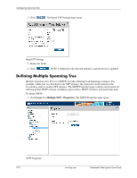
Defining Rapid Spanning Tree
 |
View all HP BladeSystem bc2800 manuals
Add to My Manuals
Save this manual to your list of manuals |
Page 120 highlights
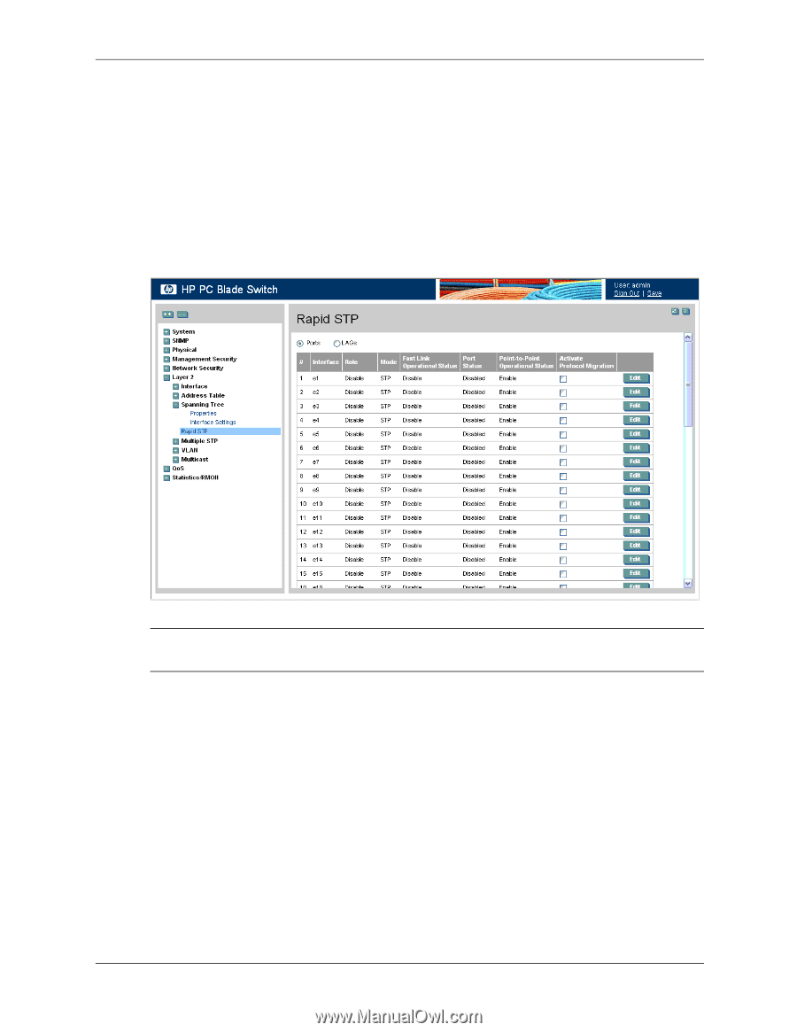
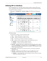
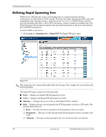
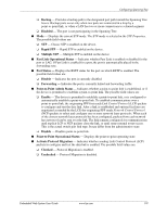
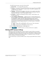
Configuring Spanning Tree Defining Rapid Spanning Tree While Classic STP prevents Layer 2 forwarding loops in a general network topology, convergence can take between 30-60 seconds. This time may delay detecting possible loops and propagating status topology changes. Rapid Spanning Tree Protocol (RSTP) detects and uses network topologies that allow a faster STP convergence without creating forwarding loops. The Global System LAG information displays the same field information as the ports, but represent the LAG RSTP information. To define RSTP on the device: 1. Click Layer 2 > Spanning Tree > Rapid STP. The Rapid STP page opens: Rapid STP ✎ This image may not contain all possible fields for this page. The complete list is provided in the following bullets. The Rapid STP page contains the following fields: ■ Ports - Displays the Rapid STP information for ports. ■ LAGs - Displays the Rapid STP information for LAGs. ■ Interface - Displays the port or LAG on which Rapid STP is enabled. ■ Role - Displays the port role assigned by the STP algorithm to provide to STP paths. The possible field values are: ❏ Root - Provides the lowest cost path to forward packets to the root switch. ❏ Designated - The port or LAG through which the designated switch is attached to the LAN. ❏ Alternate - Provides an alternate path to the root switch from the root interface. 9-8 www.hp.com Embedded Web System User Guide
-
 1
1 -
2
-
3
-
4
-
5
-
6
-
7
-
8
-
9
-
10
-
11
-
12
-
13
-
14
-
15
-
16
-
17
-
18
-
19
-
20
-
21
-
22
-
23
-
24
-
25
-
26
-
27
-
28
-
29
-
30
-
31
-
32
-
33
-
34
-
35
-
36
-
37
-
38
-
39
-
40
-
41
-
42
-
43
-
44
-
45
-
46
-
47
-
48
-
49
-
50
-
51
-
52
-
53
-
54
-
55
-
56
-
57
-
58
-
59
-
60
-
61
-
62
-
63
-
64
-
65
-
66
-
67
-
68
-
69
-
70
-
71
-
72
-
73
-
74
-
75
-
76
-
77
-
78
-
79
-
80
-
81
-
82
-
83
-
84
-
85
-
86
-
87
-
88
-
89
-
90
-
91
-
92
-
93
-
94
-
95
-
96
-
97
-
98
-
99
-
100
-
101
-
102
-
103
-
104
-
105
-
106
-
107
-
108
-
109
-
110
-
111
-
112
-
113
-
114
-
 115
115 -
 116
116 -
 117
117 -
 118
118 -
 119
119 -
 120
120 -
 121
121 -
 122
122 -
 123
123 -
 124
124 -
 125
125 -
126
-
127
-
128
-
129
-
130
-
131
-
132
-
133
-
134
-
135
-
136
-
137
-
138
-
139
-
140
-
141
-
142
-
143
-
144
-
145
-
146
-
147
-
148
-
149
-
150
-
151
-
152
-
153
-
154
-
155
-
156
-
157
-
158
-
159
-
160
-
161
-
162
-
163
-
164
-
165
-
166
-
167
-
168
-
169
-
170
-
171
-
172
-
173
-
174
-
175
-
176
-
177
-
178
-
179
-
180
-
181
-
182
-
183
-
184
-
185
-
186
-
187
-
188
-
189
-
190
-
191
-
192
-
193
-
194
-
195
-
196
-
197
-
198
-
199
-
200
-
201
-
202
-
203
-
204
-
205
-
206
-
207
-
208
-
209
-
210
-
211
-
212
-
213
-
214
-
215
-
216
 |
 |