Netgear GS516TP Software Administration Manual
Netgear GS516TP Manual
 |
View all Netgear GS516TP manuals
Add to My Manuals
Save this manual to your list of manuals |
Netgear GS516TP manual content summary:
- Netgear GS516TP | Software Administration Manual - Page 1
GS516TP Gigabit Smart Switches Software Administration Manual 350 East Plumeria Drive San Jose, CA 95134 USA June 2013 202-11259-01 v1.0 - Netgear GS516TP | Software Administration Manual - Page 2
. To register your product, get the latest product updates, get support online, or for more information about the topics covered in this manual, visit the Support website at http://support.netgear.com Phone (US & Canada only): 1-888-NETGEAR. Phone (Other Countries): Check the list of phone numbers - Netgear GS516TP | Software Administration Manual - Page 3
IP Configuration 28 IPv6 Network Configuration 29 IPv6 Network Neighbors 30 Time 31 DNS 34 Green Ethernet Configuration 35 PoE 39 PoE Global Configuration 41 PoE Port Configuration 41 PoE PD Port Status 42 Timer Global Configuration 43 SNMP 44 SNMP v1/v2 44 Trap Flags 45 SNMP Supported - Netgear GS516TP | Software Administration Manual - Page 4
GS516TP Gigabit Smart Switches DHCP Snooping Global Configuration 55 DHCP Snooping Interface Configuration 55 DHCP Snooping Table 91 Dynamic Address Configuration 92 Static MAC Address 92 Chapter 4 Configuring Routing Configure IP Settings 94 Configure VLAN Routing 95 VLAN Routing Wizard 95 4 - Netgear GS516TP | Software Administration Manual - Page 5
GS516TP Gigabit Smart Switches Configure VLAN Routing 96 Configure and View Routes 97 Configure ARP 99 ARP Entry Configuration 100 Chapter 5 Configure Quality of Service Class of Service 104 Basic CoS Configuration 104 CoS Interface Configuration 105 Queue Configuration 105 802.1p to Queue - Netgear GS516TP | Software Administration Manual - Page 6
160 System Resources Utilization 161 Chapter 8 Maintenance Reset 163 Device Reboot 163 Factory Default 163 Upload a File from the Switch 164 TFTP Troubleshooting 171 Ping 171 Ping IPv6 172 Traceroute 172 Remote Diagnostics 173 Chapter 9 Help Online Help 175 Support 175 User Guide - Netgear GS516TP | Software Administration Manual - Page 7
GS516TP Gigabit Smart Switches Registration 176 Switch Features and Defaults 179 Virtual Local Area Networks (VLANs 183 Sample VLAN Configuration 184 Access Control Lists (ACLs 185 Sample MAC ACL Configuration 185 Sample Standard IP ACL Configuration 186 Differentiated Services (DiffServ 188 - Netgear GS516TP | Software Administration Manual - Page 8
GS516TP Gigabit Smart Switches 8 - Netgear GS516TP | Software Administration Manual - Page 9
and operate the GS516TP Gigabit Smart Switches by using the web-based graphical user interface (GUI). This manual describes the software configuration procedures and explains the options available within those procedures. This switch is referred to as the NETGEAR switch throughout this document - Netgear GS516TP | Software Administration Manual - Page 10
GS516TP Gigabit Smart Switches Getting Started with the NETGEAR Switch This chapter provides an overview of starting your NETGEAR switch and downloaded to your computer. This guide does not document the SCC application. Full documentation for SCC is found at http://docs.netgear.com/scc/enu/202-10685 - Netgear GS516TP | Software Administration Manual - Page 11
GS516TP Gigabit Smart Switches Switch Management Interface The NETGEAR switch contains an embedded web server and You can configure all switch features, such as VLANs, QoS, and ACLs, by using the web-based management interface. NETGEAR provides the Smart Control Center utility with this product - Netgear GS516TP | Software Administration Manual - Page 12
GS516TP Gigabit Smart Switches Connect the Switch to the Network To enable remote management of the switch through a web browser or SNMP, you must connect the switch to the network and configure it with network information (an IP address, subnet mask, and default gateway). The switch has a default - Netgear GS516TP | Software Administration Manual - Page 13
GS516TP Gigabit Smart Switches Discover a Switch in a Network with a DHCP Server This section describes how to set up your switch in a network that has a DHCP server. The DHCP client on the switch is enabled by default. When you connect it to your network, the DHCP server automatically assigns an IP - Netgear GS516TP | Software Administration Manual - Page 14
GS516TP Gigabit Smart Switches 7. Select your switch by clicking the line that displays the switch, then click the Web Browser Access button. The Smart Control Center displays a login window. The default password is password. Use this screen to manage your switch. For more information, see Access - Netgear GS516TP | Software Administration Manual - Page 15
service. To assign a static IP address: 1. Connect the switch to your existing network. 2. Power on the switch by connecting its power cord. 3. Install the Smart Control Center on your computer. 4. Start the Smart Control Center. 5. Click Discover for the Smart Control Center to find your NETGEAR - Netgear GS516TP | Software Administration Manual - Page 16
DHCP. 8. Enter the static switch IP address, gateway IP address, and subnet mask for the switch and type your password. Tip: You must enter the current password every time you use the Smart Control Center to update the switch setting. The default password is password. 9. Click APPLY to configure the - Netgear GS516TP | Software Administration Manual - Page 17
address on the switch. For most networks, this means you must change the IP address of the administrative system to be on the same subnet as the default IP address of the switch (192.168.1.1). To change the IP address on an administrative system running a Windows operating system, open the Internet - Netgear GS516TP | Software Administration Manual - Page 18
GS516TP Gigabit Smart Switches 2. Set the IP address of the administrative system to an address in the 192.168.0.0 network, such as 192.168.0.200. The IP address must be different from the switch's address but within the same subnet. 3. Click OK. To configure a static address on the switch: 1. Use - Netgear GS516TP | Software Administration Manual - Page 19
GS516TP application at http://docs.netgear.com/scc/enu/202-10685-01/index.htm. • Open a web browser and enter the IP address of the switch browser and enter the IP address of the switch in the web browser address field. 2. The factory default password is password. Type the password in the field on - Netgear GS516TP | Software Administration Manual - Page 20
GS516TP Gigabit Smart Switches 3. After the system authenticates you, the System Information screen displays. Navigation tab Help link Configuration menus Logout button Help screen Screen menu - Netgear GS516TP | Software Administration Manual - Page 21
GS516TP Gigabit Smart Switches When you click a menu item that includes multiple configuration item configured in the heading row of a table. Sends the updated configuration to the switch. Configuration changes take effect immediately. Resets the data on the screen to the latest value of the switch - Netgear GS516TP | Software Administration Manual - Page 22
GS516TP Gigabit Smart Switches Power/Status LED The device supports ports that receive power (ports 1-8) and supply power (ports 15, 16). See PoE Global Configuration The device supports the following power LEDs. • The Power LED is a bicolor LED that serves as an indicator of power and diagnostic - Netgear GS516TP | Software Administration Manual - Page 23
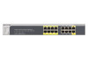
GS516TP Gigabit Smart Switches The following image shows the device view of the NETGEAR switch. Figure 2. Ports and LEDs on the manage the switch. The online help screens are context-sensitive. For example, if the IP Addressing screen is open, the help topic for that screen displays if you click Help - Netgear GS516TP | Software Administration Manual - Page 24
GS516TP Gigabit both standard public MIBs for standard functionality and private MIBs that support more switch functionality. All private MIBs begin with a hyphen (-) objects in the public MIB, IF-MIB. SNMP is enabled by default. The System Information screen, which displays after a successful login, - Netgear GS516TP | Software Administration Manual - Page 25
GS516TP Gigabit Smart Switches Interface Naming Convention The switch supports physical and logical interfaces. Interfaces are identified by their type and the interface number. The switch support the following ports: • Ports 1-8. PoE (Power over Ethernet) Power Source Equipment (PSE) ports - Netgear GS516TP | Software Administration Manual - Page 26
2. Configuring System Information 2 Use the features in the System tab to define the switch's relationship to its environment. The System tab contains links to screens described in the following sections: • Management • PoE • SNMP • LLDP • Services-DHCP Snooping 26 - Netgear GS516TP | Software Administration Manual - Page 27
GS516TP Gigabit Smart Switches Management This section describes how to display the switch status and specify some basic switch information, such as the management interface IP . You can use up to 160 alphanumeric characters. The factory default is blank. 3. Click APPLY to apply the changes to - Netgear GS516TP | Software Administration Manual - Page 28
.3 are not valid. • Subnet Mask. The IP subnet mask for the interface. The factory default value is 255.255.255.0. • Default Gateway. The default gateway for the IP interface. 4. Specify the VLAN ID for the management VLAN. The management VLAN is used to establish an IP connection to the switch from - Netgear GS516TP | Software Administration Manual - Page 29
GS516TP Gigabit Smart Switches port VLAN ID (PVID) of the port to be connected in that management VLAN be the same as the management VLAN ID. Note: Make sure that the PVID of at least one port that is a port of the VLAN is the same as the management VLAN ID. For information about creating VLANs and - Netgear GS516TP | Software Administration Manual - Page 30
GS516TP Gigabit Smart Switches address format. • EUI64. Specify whether the IPv6 address is in EUI-64 format. The default value is False. 3. Click ADD to add a new IPv6 address, or click DELETE to until a confirmation is received. • Last Updated. Elapsed time since the address was last confirmed as - Netgear GS516TP | Software Administration Manual - Page 31
GS516TP Gigabit Smart Switches Time The switch software supports the Simple Network Time Protocol (SNTP). You can also set the system time manually Polling for unicast information is used for polling a server for which the IP address is known. SNTP servers that have been configured on the device are - Netgear GS516TP | Software Administration Manual - Page 32
GS516TP Gigabit Smart Switches 3. In the Date field, enter the date in the DD/MM/YYYY SNTP Global Status fields. Table 2. SNTP Global Status fields. Field Version Supported Mode Last Update Time Server IP Address Address Type Server Stratum Server Mode Description Specifies the SNTP version the - Netgear GS516TP | Software Administration Manual - Page 33
GS516TP Gigabit Smart Switches Field Unicast Address. Enter the IP address or the host name of the SNTP server. • Port. Enter a port number on the SNTP server to which SNTP requests are sent. The valid range is 1-65535. The default is 123. 3. . The entry is removed, and the device is updated. 33 - Netgear GS516TP | Software Administration Manual - Page 34
field is provided as the domain name. For example, if the default domain name is netgear.com and the host name to resolve is test, test.netgear.com is used in DNS resolution queries. 4. in the DNS Server field, enter an IP address representing the DNS server to which the switch sends DNS queries - Netgear GS516TP | Software Administration Manual - Page 35
the IP address associated with the host name. Click CLEAR to delete dynamic host entries. The table repopulates with entries as they are learned. Green Ethernet Configuration The Green Ethernet features allow the switch to reduce power consumption on a per-port basis. Each switch can support one - Netgear GS516TP | Software Administration Manual - Page 36
GS516TP are put into the low-power mode so only enough power is used to support a short cable. • Disable. Provide full power to the PHY regardless of cable Mode. Determines whether Short Cable mode is enabled for the port. The factory default is Disable. When the port link up at 1 Gbps, the cable - Netgear GS516TP | Software Administration Manual - Page 37
GS516TP Gigabit Smart Switches Green Ethernet Detail Use this screen to display or configure Green Ethernet details per interface. To configure the Green Ethernet Detail feature: 1. - Netgear GS516TP | Software Administration Manual - Page 38
GS516TP Gigabit Smart Switches Green Ethernet Summary This screen summarizes the Green Ethernet Summary settings currently in use. To access the Green Ethernet Summary screen, select - Netgear GS516TP | Software Administration Manual - Page 39
GS516TP Gigabit Smart Switches PoE A Power over Ethernet (PoE) device is power sourcing equipment (PSE) that delivers electrical power to connected powered devices (PDs) over existing copper cables without interfering with the network traffic, updating the physical network, or modifying the network - Netgear GS516TP | Software Administration Manual - Page 40
GS516TP Gigabit Smart Switches • Per-port priority settings, timers, and power to a PD whose power class determines the maximum amount of power required. The following describes these classes: Table 6. PoE PSE Classes Class Available Power 0 0-15.4W 1 0-4W 2 0-7W 3 0-15.4W Each PD port ( - Netgear GS516TP | Software Administration Manual - Page 41
GS516TP Gigabit Smart Switches PoE Global Configuration The PoE feature can be globally configured to generate the amount of consumed power. To enable or disable PoE traps: 1. Select System > PoE > Advanced > PoE Configuration. 2. Select the appropriate radio button to enable or disable - Netgear GS516TP | Software Administration Manual - Page 42
GS516TP Power is being drawn by a connected device. • Fault. There is a problem with the port. • Test. The port is in test mode. • OtherFault • Searching. Port default state when PD not connected. To configure PoE on ports 1-8: 1. Select System > PoE > Advanced > PoE Port Configuration. 2. - Netgear GS516TP | Software Administration Manual - Page 43
GS516TP Gigabit Smart Switches • Mode. PD • Class. Class of connected device, either : • Class 0 - 15 in the Timer Schedule Name field. c. Click ADD. 2. Configure the timer: a. Select System > PoE > Advanced > Timer Schedule Configuration. b. From the Timer Schedule Name list, select one of the - Netgear GS516TP | Software Administration Manual - Page 44
Supported MIBs • SNMP v3 User Configuration SNMP v1/v2 The screens you access from the SNMPv1/v2 link allow you to configure SNMP community information, traps, and trap flags. Community Configuration By default Station IP or Management Station IP Mask) is 0.0.0.0, access is allowed from any IP - Netgear GS516TP | Software Administration Manual - Page 45
GS516TP Gigabit Smart Switches • Management Station IP Mask. Specify the subnet mask to associate with the management station IP address. • traps: 1. Enter trap configuration information in the following fields: • Recipients IP. The address in x.x.x.x format to receive SNMP traps from this device. - Netgear GS516TP | Software Administration Manual - Page 46
failure traps by selecting the corresponding button. The factory default is Enable. 4. Click APPLY. Configuration changes take effect immediately. SNMP Supported MIBs The screen allows you to view a list of the supported MIBs. To access the Supported MIBS screen, select System > SNMP > SNMP v1/v2 - Netgear GS516TP | Software Administration Manual - Page 47
GS516TP Gigabit the following features: • Autodiscovery of LAN policies (such as VLAN, Layer 2 Priority, and DiffServ settings), enabling plug and play TLV Advertised Interval. Specify the interval at which frames are transmitted. The default is 30 seconds, and the valid range is 5-32768 seconds. • - Netgear GS516TP | Software Administration Manual - Page 48
and receiving LLDP PDUs on the selected ports. This value is the default value. • Disabled. Do not transmit or receive LLDP PDUs on the selected ports. • Management IP Address. Select whether to advertise the management IP address from the interface. The possible values are: • Stop Advertise. Do not - Netgear GS516TP | Software Administration Manual - Page 49
GS516TP Gigabit Smart Switches LLDP-MED Network Policy This screen displays information type associated with the policy. Only the Voice application type is supported. The application type that is received on the interface has the VLAN ID, priority, DSCP, tagged bit status, and unknown bit status - Netgear GS516TP | Software Administration Manual - Page 50
GS516TP Gigabit Smart Switches Local Information Use the LLDP Local Information screen to view Displays the number that identifies the port. MAC/PHY Details Auto-Negotiation Supported Specifies whether the interface supports port-speed auto negotiation. Possible values are True and False. Auto- - Netgear GS516TP | Software Administration Manual - Page 51
GS516TP Gigabit Smart Switches Field Operational MAU Type MED Details Capabilities Supported Current Capabilities Device Class Network Policies Application Type VLAN ID VLAN Subtype Chassis ID Port ID Subtype Description Displays the Media Service Access Point (MSAP) entry number for the remote - Netgear GS516TP | Software Administration Manual - Page 52
GS516TP Gigabit Smart Switches Field Description Port ID Identifies the physical address interface on the local system that received LLDP information from a remote system. Displays the Media Service Access Point (MSAP) entry number for the remote device. Identifies the type of data displayed in - Netgear GS516TP | Software Administration Manual - Page 53
support, and device information management capabilities. Hardware Revision The hardware version advertised by the remote device. Firmware Revision The firmware latitude, longitude, and altitude. ECS ELIN The Emergency Call Service (ECS) Emergency Location Identification Number (ELIN) the remote - Netgear GS516TP | Software Administration Manual - Page 54
GS516TP Gigabit Smart Switches Field Network Policies Application Type VLAN ID VLAN Type User Priority DSCP LLDP Unknown TLVs Type Value Description The media application type associated with the policy advertised by the remote device. The VLAN ID associated with the policy. Specifies whether the - Netgear GS516TP | Software Administration Manual - Page 55
GS516TP Gigabit Smart Switches Services- binding table contains the MAC address, IP address, lease time, binding type, VLAN number, and interface information that corresponds to enable or disable the DHCP snooping feature for entered VLAN. The factory default is disabled. 6. Click APPLY to apply the - Netgear GS516TP | Software Administration Manual - Page 56
GS516TP Gigabit Smart Switches To configure DHCP snooping interface settings: 1. Select System > Services . The factory default is disabled VLAN ID list, select the VLAN from the list for the binding rule. The valid range of the VLAN ID is 1-4093. 5. In the IP Address field, specify a valid IP - Netgear GS516TP | Software Administration Manual - Page 57
Switches Field IP Address Lease Time Description The IP address for the binding entry in the binding database. The remaining lease time for the dynamic binding entries. DHCP Snooping Persistent Configuration To configure DHCP snooping persistent settings: 1. Select System > Services > DHCP - Netgear GS516TP | Software Administration Manual - Page 58
access from the Switching tab to define Layer 2 features. The Switching tab contains links to features described in the following sections: • Ports • Link Aggregation Groups • VLANs • Voice VLAN • Auto-VoIP Configuration • Spanning Tree Protocol • Multicast • Forwarding Database 58 - Netgear GS516TP | Software Administration Manual - Page 59
default is Disable. • Enable. The switch sends pause packets if the port buffers become full. • Disable. The switch does not send pause packets if the port buffers become full. 3. View the Jumbo Frames Status. 4. In the Jumbo Frames After Reset list, select Enable or Disable. Jumbo frames support - Netgear GS516TP | Software Administration Manual - Page 60
GS516TP Gigabit Smart Switches 3. Select the check box next to the port or 1000 Mbps) is advertised. Otherwise, your selection determines the port's duplex mode and transmission rate. The factory default is Auto. • Physical Status. Indicates the physical port's speed and duplex mode. • Link Status - Netgear GS516TP | Software Administration Manual - Page 61
GS516TP VLAN. A LAG interface can be either static or dynamic, but not both. All members of a LAG must participate in the same protocols. A static port channel interface does not require a partner system to be able to aggregate its member ports. Static LAGs are supported The factory default is Enable - Netgear GS516TP | Software Administration Manual - Page 62
GS516TP Gigabit Smart Switches member ports do not transmit LAGPDUs and all the LAGPDUs it might receive are dropped. The default is Static. • Active with ports g1-g4 as members. 5. Click APPLY to send the updated configuration to the switch. Configuration changes take effect immediately. 6. To - Netgear GS516TP | Software Administration Manual - Page 63
GS516TP Gigabit Smart Switches LACP Configuration To configure LACP: 1. Select Switching > LAG > parameter globally by specifying a priority from 1 to 65535. The default value is 32768. 3. Click APPLY to send the updated configuration to the switch. Configuration changes take effect immediately. - Netgear GS516TP | Software Administration Manual - Page 64
the following sections: • VLAN Configuration • VLAN Membership Configuration • Port VLAN ID Configuration VLAN Configuration Use the VLAN Configuration screen to define VLAN groups stored in the VLAN membership table. The switch supports up to 256 VLANs. VLAN 1 is created by default, and all ports - Netgear GS516TP | Software Administration Manual - Page 65
GS516TP Gigabit Smart Switches To reset VLAN settings on the switch to the factory defaults: 1. Select the Reset Configuration check box 2. Click OK in the pop-up message to confirm the operation. If the Management VLAN is set to a non-default VLAN (VLAN 1), it is automatically set to 1 after you - Netgear GS516TP | Software Administration Manual - Page 66
. The factory default is Enable. • Disable. All frames are forwarded in accordance with the IEEE 802.1Q VLAN standard. 6. In the Port Priority field, specify the default 802.1p priority assigned to untagged packets arriving at the port. Possible values are 0-7. 7. Click APPLY to send the updated - Netgear GS516TP | Software Administration Manual - Page 67
the switch. If the switch does not handle traffic from IP phones, the status must be disabled. 3. From the Voice VLAN ID list, select the voice VLAN ID to use for voice traffic. The default value is 2. 4. In the Class of Service list, select the CoS tag value to be reassigned for packets received - Netgear GS516TP | Software Administration Manual - Page 68
GS516TP Gigabit Smart Switches 3. Go To Interface. Enter the port to be configured and click the GO button. 4. From the Voice VLAN Mode list, specify whether to enable or disable voice VLAN on the selected port. 5. Click APPLY to send the updated configuration to the switch. Note: The Membership - Netgear GS516TP | Software Administration Manual - Page 69
GS516TP only the SIP and SCCP protocols are checked. This feature supports up to 48 bidirectional VoIP calls. VoIP frames that are are active at the same time on the same port, the manual QoS assignment might override the VoIP QoS assignment. To configure the updated configuration to the switch. 69 - Netgear GS516TP | Software Administration Manual - Page 70
loops. For information about configuring Common STP, see CST Port Configuration . Multiple Spanning Tree Protocol (MSTP) supports multiple instances of spanning tree to efficiently channel VLAN traffic over different interfaces. Each instance of the spanning tree behaves in the manner specified in - Netgear GS516TP | Software Administration Manual - Page 71
GS516TP Gigabit Smart Switches 3. currently being used. The valid range is 0-65535. The default value is 0. 5. The Forward BPDU while STP Disabled field Select Enable or Disable. 6. Click APPLY to send the updated configuration to the switch. Configuration changes take place immediately. The - Netgear GS516TP | Software Administration Manual - Page 72
GS516TP through 4095, it is set to 0. The valid range is 0-61440. The default priority is 32768. • Bridge Max Age (Sec). Specify the bridge maximum age is 1-40. 3. Click APPLY to send the updated configuration to the switch. Configuration changes take place VLAN IDs associated with each of them. 72 - Netgear GS516TP | Software Administration Manual - Page 73
GS516TP Gigabit Smart Switches Field VID FID Description Table consisting of the VLAN IDs and the corresponding FID associated with each of them. Table consisting of the FIDs and the corresponding VLAN default updated configuration to the switch. Configuration changes take place immediately. 73 - Netgear GS516TP | Software Administration Manual - Page 74
GS516TP Gigabit Smart Switches CST Port Status To display Common Spanning Tree Forwarding State Description Select a physical or port channel interface to configure. The port is associated with the VLANs associated with the CST. Each MST Bridge Port that is enabled is assigned a port role for each - Netgear GS516TP | Software Administration Manual - Page 75
GS516TP Gigabit Smart Switches Rapid STP Use the Rapid STP screen to view The default priority is 32768.The valid range is 0-61440. • VLAN ID. The list contains all VLANs configured on the switch. Select a VLAN to associate with the MST instance. 3. Click APPLY to send the updated configuration - Netgear GS516TP | Software Administration Manual - Page 76
GS516TP Gigabit Smart Switches 2. Click APPLY to send the updated configuration to the switch. Configuration changes take place immediately. To delete an MST instance, select the check box next to the instance and click DELETE. - Netgear GS516TP | Software Administration Manual - Page 77
GS516TP Gigabit Smart Switches 4. Configure the MST values for the selected ports or LAGs: • If you enter 0, the device recalculates the path cost. 5. Click APPLY to send the updated configuration to the switch. Configuration changes take place immediately. The following table describes the read- - Netgear GS516TP | Software Administration Manual - Page 78
GS516TP Gigabit Smart Switches Field Designated Bridge Designated Port Description Bridge identifier of the bridge with the designated port. It is made up using the bridge - Netgear GS516TP | Software Administration Manual - Page 79
GS516TP Gigabit Smart Switches Multicast Multicast IP traffic is traffic that is destined to a host traffic is unnecessary. When a packet enters the switch, the destination MAC address is combined with the VLAN ID, and a search is performed in the Layer 2 Multicast Forwarding Database. If no match is - Netgear GS516TP | Software Administration Manual - Page 80
GS516TP Gigabit Smart Switches Address. The multicast MAC address for which you requested data. • VLAN ID. The VLAN ID to which the multicast MAC address is related. • Component. MFDB table. Auto-Video Configuration If the switch supports devices or applications running multicast traffic, the Auto- - Netgear GS516TP | Software Administration Manual - Page 81
VLANs. 3. Click APPLY to send the updated configuration to the switch. Configuration changes take place immediately. IGMP Snooping Internet Group Management Protocol (IGMP) snooping is a feature that allows a switch to forward Multicast traffic intelligently on the switch. Multicast IP The problem - Netgear GS516TP | Software Administration Manual - Page 82
GS516TP Gigabit Smart Switches To configure are processed. 4. Click APPLY to send the updated configuration to the switch. Configuration changes take place by colons, for example, 01:00:5e:45:67:89. A VLAN ID for which the switch has forwarding and filtering information. This field displays - Netgear GS516TP | Software Administration Manual - Page 83
GS516TP that group. Also, fast leave processing is supported only with IGMP version 2 hosts. • Host Timeout. VLAN ID. • Query Interval. Enter the value for IGMP query interval for the specified VLAN ID. The valid range is 30-1800 seconds. The default is 60 seconds. 3. Click APPLY to send the updated - Netgear GS516TP | Software Administration Manual - Page 84
GS516TP Querier Address field, specify the IP address to be used as the VLAN on which the query is being sent. 4. In the IGMP Version field, specify the IGMP protocol version used in periodic IGMP queries. Only version 2 is supported default the value is: 2*60+5 =125. 7. Click APPLY to send the updated - Netgear GS516TP | Software Administration Manual - Page 85
other querier moves to non-querier state. • Snooping Querier VLAN Address. Specify the snooping querier IP address to be used as the source address in periodic IGMP queries sent on the specified VLAN. 3. Click APPLY to send the updated configuration to the switch. Configuration changes take place - Netgear GS516TP | Software Administration Manual - Page 86
GS516TP Gigabit Smart Switches Table 22. Querier VLAN Status Fields Field VLAN ID Operational State Operational Version Operational Max Response Time Description Specifies the VLAN ID on which the IGMP snooping querier is administratively enabled and for which VLAN exists in the VLAN database. - Netgear GS516TP | Software Administration Manual - Page 87
GS516TP Gigabit Smart Switches that want to receive the data, instead of being flooded to all ports in a VLAN. This list is constructed by snooping IPv6 default is disabled. The VLAN IDs Enabled For MLD Snooping section displays VLAN IDs enabled for MLD snooping. 3. Click APPLY to send the updated - Netgear GS516TP | Software Administration Manual - Page 88
router attached interface list if the interface is active and is a member of the VLAN. As is not the case in the previous release of the system firmware, snooping dynamic learning mode (snooping interface mode or snooping VLAN mode) does not need not to be enabled on the interface. The dynamic - Netgear GS516TP | Software Administration Manual - Page 89
currently a member of this multicast group on this VLAN. Note: If an interface was added to the Multicast group as a result of IGMP/MLD snooping, its status is Dynamic. This status cannot be selected manually. 5. Click APPLY to send the updated configuration to the switch. Multicast Forward All The - Netgear GS516TP | Software Administration Manual - Page 90
GS516TP Gigabit Smart Switches • To configure the multicast group for a link aggregation group (LAG), click LAGS. • To Multicast group as a result of IGMP/MLD snooping, its status is Dynamic. This status cannot be selected manually. 5. Click APPLY to send the updated configuration to the switch. 90 - Netgear GS516TP | Software Administration Manual - Page 91
GS516TP Gigabit Smart Switches Forwarding Database The forwarding database maintains a list Address Table. 2. In the Search By field, select whether to search for MAC addresses by MAC address, VLAN ID, or interface. • MAC Address: Select MAC Address and enter a 6-byte hexadecimal MAC address in 2- - Netgear GS516TP | Software Administration Manual - Page 92
GS516TP Gigabit Smart Switches Field Interface Status Description The port where this before deleting a learned entry that has not been updated. You can enter any number of seconds from 10 through 630. The factory default is 300. Click CANCEL to reset the data to the latest value of the switch. - Netgear GS516TP | Software Administration Manual - Page 93
NETGEAR switch supports IP routing. Use the menus in the Routing tab to manage routing on the system. This chapter contains the following sections: • Configure IP Settings • Configure VLAN to the next hop specified in the default route. If there is no default route configured, the packet is passed to - Netgear GS516TP | Software Administration Manual - Page 94
switch before you can route through any of the interfaces. Routing is enabled or disabled per VLAN interface. The default value is router mode. 3. Click APPLY to send the updated configuration to the switch. Switching a routing mode requires a reboot. The configuration file is not deleted during - Netgear GS516TP | Software Administration Manual - Page 95
You can configure the software with some ports supporting VLANs and some supporting routing. You can also configure the software to allow traffic on a VLAN to be treated as if the VLAN were a router port. When a port is enabled for bridging (default) rather than routing, all normal bridge processing - Netgear GS516TP | Software Administration Manual - Page 96
6. Click APPLY to send the updated configuration to the switch. Configuration changes take place immediately. Configure VLAN Routing Use the VLAN Routing Configuration screen to view information about the VLAN routing interfaces configured on the system or to assign an IP address and subnet mask to - Netgear GS516TP | Software Administration Manual - Page 97
GS516TP Gigabit Smart Switches Configure and View Routes From the Routing Table screen, you can configure static and default routes and view the routes that the NETGEAR Indicates whether the learned route is a static or default route. The IP route prefix for the destination. Also referred to as - Netgear GS516TP | Software Administration Manual - Page 98
GS516TP Gigabit Smart Switches Field Next Hop Interface Next Hop IP Address Preference Description The outgoing router interface to use when forwarding traffic to the destination. The outgoing router IP address to use when forwarding traffic to the next router (if any) in the path towards the - Netgear GS516TP | Software Administration Manual - Page 99
always replaces existing content in the ARP cache. The NETGEAR switch support 1024 ARP entries in switch mode and approximately 100 in router mode. These entries include dynamic and static ARP entries. Devices can be moved in a network, which means the IP address that was at one time associated with - Netgear GS516TP | Software Administration Manual - Page 100
GS516TP Gigabit Smart Switches ARP Cache associated with one of the switch's routing interface's MAC addresses. • Gateway. A dynamic ARP entry whose IP address is that of a router. • Static. An ARP entry configured by the user. • Dynamic. switch are displayed in the Routing VLANs ARP Cache Table. 100 - Netgear GS516TP | Software Administration Manual - Page 101
GS516TP Gigabit Smart Switches Global ARP Configuration Use the Global ARP Configuration screen to to age out. The valid range is 15 - 21,600 seconds. The default value is 1200 seconds. 3. Click APPLY to send the updated configuration to the switch. Configuration changes take place immediately. 101 - Netgear GS516TP | Software Administration Manual - Page 102
GS516TP Gigabit Smart Switches ARP Entry Management Use this screen to remove entries from the ARP entry from the ARP table. If you select Specific Entry in the Remove from Table list, you can enter the IP address of an entry to remove from the ARP table. • None. Select if you do not want to delete - Netgear GS516TP | Software Administration Manual - Page 103
preference to certain packets over others based on user-defined criteria. When a packet is queued for transmission in a port, the rate at which it is serviced depends on how the queue is configured and possibly the amount of traffic present in the other queues of the port. If a delay is necessary - Netgear GS516TP | Software Administration Manual - Page 104
GS516TP Gigabit Smart Switches Class of Service The Class of Service per port are supported. From the Class of Service menu under to be of any use, so default actions are performed when this is not such as when a non-IP packet arrives at a port configured to trust the IP DSCP value. To configure - Netgear GS516TP | Software Administration Manual - Page 105
GS516TP Gigabit field are called the Differentiated Services Code Point (DSCP) bits. 3. Click APPLY to send the updated configuration to the switch. rate (Kb) value is the value of the interface shaping rate configured. The default value is 0. The value 0 means that the maximum is unlimited. 5. In - Netgear GS516TP | Software Administration Manual - Page 106
GS516TP Gigabit Smart Switches To configure CoS queue settings: 1. Select QoS > CoS > • Weighted. Weighted round robin associates a weight to each queue. This association is the default. • Strict. Services traffic with the highest priority on a queue first. • Queue Management Type. Displays the - Netgear GS516TP | Software Administration Manual - Page 107
GS516TP Gigabit Smart Switches DSCP to Queue Mapping Use the DSCP to Queue Mapping screen to specify which internal traffic class to map to the corresponding - Netgear GS516TP | Software Administration Manual - Page 108
GS516TP Gigabit Smart Switches Differentiated Services The QoS feature provides Differentiated Services (DiffServ) support that enables traffic to be classified into streams and given certain QoS treatment in accordance with defined per-hop behaviors. For more information, see DiffServ - Netgear GS516TP | Software Administration Manual - Page 109
GS516TP occurs, the switch remaps the original DSCP value of the violate action IP packets with a new value based on the DSCP Violate Action Mapping between trusted QoS domains. For example, assume that there are three levels of service- A, B, and C and the DSCP incoming values used to mark these - Netgear GS516TP | Software Administration Manual - Page 110
GS516TP name. 3. Select the class type, and click Add. The switch supports only the Class Type value All, which means all the various match can be configured. • Class of Service. Select a Class of Service 802.1 p user priority value to be matched. • VLAN. Select a VLAN ID to be matched. • Ethernet - Netgear GS516TP | Software Administration Manual - Page 111
and a port ID field appears. • Service Type: • IP DSCP. Select the DSCP type from updated configuration to the switch. Configuration changes occur immediately. IPv6 Class Configuration The IPv6 Class Configuration feature extends the existing QoS ACL and DiffServ functionality by providing support - Netgear GS516TP | Software Administration Manual - Page 112
GS516TP Gigabit Smart Switches The switch supports only the Class Type value All, which means known destination Layer 4 ports. If you select Other, enter a protocol number in the field that appears. • IP DSCP. Select a known DSCP value. If you select Other, enter a protocol number in the field that - Netgear GS516TP | Software Administration Manual - Page 113
GS516TP • Mark VLAN CoS. Select the specified Class of Service queue number to Service value in the priority field of the 802.1p header. If the packet does not already contain this header, one is inserted. • Mark IP DSCP. Select an IP color blind, which is the default. • Committed Rate. The committed - Netgear GS516TP | Software Administration Manual - Page 114
GS516TP Gigabit Smart Switches • Send. (Default) These that the Mark CoS value field be set. • Mark IP DSCP. These packets are marked by DiffServ with the the updated configuration to the switch. Configuration changes take effect immediately. Service Configuration Use the Service Configuration - Netgear GS516TP | Software Administration Manual - Page 115
GS516TP Gigabit Smart Switches • Interface. The interface for which service statistics display. • Direction. The direction of packets for which service the selected interface. • Operational Status. The operational status of this service interface, which is either Up or Down. • Member Classes. Selects - Netgear GS516TP | Software Administration Manual - Page 116
6. Managing Device Security 6 Use the features available from the Security tab to configure management security settings for port, user, and server security. The Security tab contains links to screens described in the following sections: • Management Security Settings • Configure Management Access - Netgear GS516TP | Software Administration Manual - Page 117
of a lost password, press the Factory Default Reset button on the front panel for more than two seconds to restore the factory default. The reset button only reboots the device. Configure RADIUS Settings RADIUS servers provide authentication, authorization, and accounting services for networks. The - Netgear GS516TP | Software Administration Manual - Page 118
GS516TP Gigabit Smart Switches information. The switch passes information to the configured RADIUS server, which can authenticate a user name and password IP Address field is blank if no servers are configured (see RADIUS Server Configuration ). The switch supports is 1-15 and the default is 3. 3. In - Netgear GS516TP | Software Administration Manual - Page 119
IP address of the RADIUS server to add. 3. In the Authentication Port field, specify the UDP port number the server uses to verify the RADIUS server authentication. The valid range is 0-65535. The default box next to the server address field, update the desired fields, and click APPLY. Accounting - Netgear GS516TP | Software Administration Manual - Page 120
services: • Authentication. Provides authentication during login using user names and user-defined passwords 1-30 seconds. The default is 5 seconds. 4. Click APPLY to update the switch with the link. 2. In the TACACS+ Server field, enter the IP address of the server to add 3. In the Priority field - Netgear GS516TP | Software Administration Manual - Page 121
GS516TP Gigabit Smart Switches 5. In the Key String field, specify the authentication the connection between the device and the TACACS+ server times out. The field range is 1-30 seconds. The default value is 5. 7. Click ADD. Note: The ADD option is available if fewer than five TACACS+ servers are - Netgear GS516TP | Software Administration Manual - Page 122
GS516TP Gigabit Smart Switches HTTP Authentication List Use the HTTP Authentication List to configure the default HTTP login list. To change the HTTP authentication method for the default • RADIUS. The user's ID and password is authenticated using the RADIUS server. to update the switch with - Netgear GS516TP | Software Administration Manual - Page 123
GS516TP Gigabit Smart Switches To change the HTTPS authentication method for the default list: 1. Select more than one method. • RADIUS. The user's ID and password is authenticated using the RADIUS server. If you select RADIUS or update the switch with the HTTPS Authentication settings. 123 - Netgear GS516TP | Software Administration Manual - Page 124
GS516TP Gigabit Smart Switches Configure Management Access From the Access tab, you can the password to access the management interface. A value of zero corresponds to an infinite timeout. The default value is 5 minutes. The Maximum Number of HTTP Sessions is 5. 3. Click APPLY to update the - Netgear GS516TP | Software Administration Manual - Page 125
time, the administrator is automatically logged out and must reenter the password to access the management interface. The default value is 5 minutes. The Maximum Number of HTTPS Sessions is 2. 5. Click APPLY to update the switch with the HTTPS Authentication settings. Certificate Management Use this - Netgear GS516TP | Software Administration Manual - Page 126
GS516TP Gigabit Smart must be deactivated before removal. 4. Click APPLY to update the switch with the new settings. The Profile Summary service type. 4. In the Source IP Address field, enter the IP address from which traffic is originated. 5. In the Mask field, enter the IP mask of the source IP - Netgear GS516TP | Software Administration Manual - Page 127
GS516TP under bidirectional control. This mode is the default authentication mode. The 802.1x network has the user is authorized to access system services. From the Port Authentication menu, the system, to enable, or disable the Guest VLAN (which allows unauthenticated users to have limited access to - Netgear GS516TP | Software Administration Manual - Page 128
GS516TP VLAN, select the guest VLAN ID. 5. Enter the Guest VLAN Period. 6. Next to the EAPOL Flood Mode field, select whether to enable or disable radio button forwarding of EAPoL frames when 802.1x is disabled on the device. 7. Click APPLY to update services to the client through the interface. 128 - Netgear GS516TP | Software Administration Manual - Page 129
the port in the next field in this page. • Guest VLAN. Enable or disable the Guest VLAN on the interface. • Periodic Reauthentication. Enable or disable reauthentication of the supplicant for the specified port. The default value is Disable. Changing the selection does not change the configuration - Netgear GS516TP | Software Administration Manual - Page 130
GS516TP Gigabit Smart Switches • Connecting • Authenticating • Authenticated • Success • Fail • Timeout • Initialize • Idle 5. Click APPLY to update the switch with the new settings. Port Summary Use the Port Summary screen provide authentication services to the client through the interface. 130 - Netgear GS516TP | Software Administration Manual - Page 131
GS516TP Gigabit Smart Switches Field Operating Control Mode Reauthentication Enabled Port Status Description Indicates the control mode under which the port is actually operating. The possible - Netgear GS516TP | Software Administration Manual - Page 132
GS516TP Gigabit Smart Switches Traffic Control From the Traffic Control menu, you can configure MAC packets are forwarded. The range is a percentage of the total threshold between 0-100%. The default is 5%. Storm control is configured as a percentage of the maximum port speed. 6. Click APPLY to - Netgear GS516TP | Software Administration Manual - Page 133
GS516TP interface. The valid range is 0-600. The default value is 600. • Enable Violation Traps. Select on a locked port. 5. Click APPLY to update the switch with the new settings. Security MAC Table section shows the MAC addresses and their associated VLANs learned on the selected port. Use the Port - Netgear GS516TP | Software Administration Manual - Page 134
GS516TP Gigabit Smart Switches Table 26. Dynamic MAC addresses table fields. Field VLAN ID MAC Address Description The VLAN ID corresponding to the last violation two protected ports. 4. Click APPLY to update the switch with the new settings. Configuration changes take effect immediately. 134 - Netgear GS516TP | Software Administration Manual - Page 135
GS516TP updates, decide which types of traffic are forwarded or blocked, and above all provide security for the network. The switch software supports IP ACL • IP Rules • IP Extended Rules • IPv6 ACL • IPv6 Rules • IP Binding Configuration • IP instructions VLAN. • ACL Based on Source MAC. - Netgear GS516TP | Software Administration Manual - Page 136
GS516TP Gigabit Smart Switches • ACL Based on Destination IPv4. Creates an ACL based on the destination IPv4 address and IPv4 address mask. • ACL Based on Source - Netgear GS516TP | Software Administration Manual - Page 137
:xx:xx:xx:xx:xx). Destination IPv4 • Destination IP Address. Specify the destination IP address. • Destination IP Mask. Specify the destination IP address mask. Source IPv4 • Source IP Address. Specify the source IP address. • Source IP Mask. Specify the source IP address mask. Destination IPv6 - Netgear GS516TP | Software Administration Manual - Page 138
GS516TP Gigabit Smart a MAC ACL, select the check box next to the Name field, update the name, then click APPLY. MAC Rules Use the MAC Rules screen that specify whether traffic matching the criteria is forwarded normally or discarded. A default 'deny all' rule is the last rule of every list. To - Netgear GS516TP | Software Administration Manual - Page 139
GS516TP Gigabit Smart Switches • Match Every. Requires a packet to match the criteria of this ACL. Select Enable or Disable. Match Every is exclusive to the other filtering rules, so if Match Every is True, the other rules on the screen are not available. • CoS. Requires a packet's Class of Service - Netgear GS516TP | Software Administration Manual - Page 140
GS516TP Gigabit Smart Switches To configure MAC ACL interface bindings: 1. Select Security > ACL > . An √ in the box indicates that the ACL is applied to the interface. 5. Click APPLY to update the switch with the new settings. MAC Binding Table Use the MAC Binding Table screen to view or delete - Netgear GS516TP | Software Administration Manual - Page 141
the ACL as either a standard or extended IP ACL. 3. Click ADD. To change the name of an IP ACL, select the check box next to the IP ACL ID field, update the name, then click APPLY. IP Rules Use the IP Rules screen to define rules for IP-based standard ACLs. The access list definition includes - Netgear GS516TP | Software Administration Manual - Page 142
GS516TP Gigabit Smart Switches To configure IP rules, select the following: 1. Select Security > ACL > Advanced > IP Rules. 2. From the ACL ID field, select the IP ACL for which to create or update a rule. The valid range is 1-99. 3. Configure the following fields: • Rule ID. Specify a number from - Netgear GS516TP | Software Administration Manual - Page 143
GS516TP Gigabit Smart Switches Note: There is an implicit "deny all" rule at the table. 3. Configure the fields for the new rule. • Rule ID. Specify a number from 1 to 10 to identify the IP ACL rule. You can create up to ten rules for each ACL. • Action. Select an ACL forwarding action: • Permit. - Netgear GS516TP | Software Administration Manual - Page 144
, enter a user-defined port ID by which packets are matched to the rule. • Service Type. Select one of the Service Type match conditions for the extended IP ACL rule. The possible values are IP DSCP, IP precedence, and IP ToS, which are alternative ways of specifying a match criterion for the same - Netgear GS516TP | Software Administration Manual - Page 145
GS516TP Gigabit Smart Switches • The number of the rules associated with the IP lists are created using the IPv6 ACL screen. By default, no specific value is in effect for any of list in the ACL Name field, select the IP ACL for which to create or update a rule. 3. Configure the settings for the new - Netgear GS516TP | Software Administration Manual - Page 146
GS516TP Gigabit Smart start and end of a port range. • IPv6 DSCP Service. Select the IPv6 DSCP service. If you prefer, you can select the Other option in the changes to the switch. Configuration changes take effect immediately. IP Binding Configuration When an ACL is bound to an interface, all - Netgear GS516TP | Software Administration Manual - Page 147
GS516TP Gigabit Smart Switches • To add the selected ACL to a port or LAG, click to the running configuration. IP Binding Table Use the IP Binding Table screen to view or delete the IP ACL bindings. To display the IP Binding Table, click Security ACL > Advanced IP Binding Table. Table 29 - Netgear GS516TP | Software Administration Manual - Page 148
7. Monitoring the System 7 Use the features available from the Monitoring tab to view various information about the switch and its ports and to configure how the switch monitors events. The Monitoring tab contains menus that provide access to the following features: • Ports • Logs • Mirroring • - Netgear GS516TP | Software Administration Manual - Page 149
GS516TP Gigabit Smart Switches Ports The screens available from the Ports menu contain various information about the number and type of traffic transmitted from and received - Netgear GS516TP | Software Administration Manual - Page 150
GS516TP Gigabit Smart Switches • Address Entries in Use. The number of Learned and static entries in the Forwarding Database Address Table for this switch. • Maximum VLAN Entries. The maximum number of virtual LANs (VLANs) allowed on this switch. • Static VLAN Entries. The number of presently active - Netgear GS516TP | Software Administration Manual - Page 151
GS516TP Gigabit Smart Switches Port Detailed Statistics The Port Detailed Statistics screen • Admin Mode. The port control administration state: • Enable. The port can participate in the network (default). • Disable. The port is administratively down and does not participate in the network. 151 - Netgear GS516TP | Software Administration Manual - Page 152
GS516TP Gigabit Smart Switches • LACP Mode. The Link Aggregation Control Protocol administration state: • Enable. The port is allowed to participate in a port channel (LAG), which is the default to send a trap when link status changes. The factory default is Enable. • Enable. The system sends a trap - Netgear GS516TP | Software Administration Manual - Page 153
GS516TP Gigabit Smart Switches • Total Packets Received with MAC Errors. The total number of inbound packets that contained errors preventing them from being deliverable to a higher- - Netgear GS516TP | Software Administration Manual - Page 154
GS516TP Gigabit Smart Switches • Tx Oversized. The total number of frames that bottom of the screen to perform the following actions: • Click CLEAR to clear all the counters. This resets all statistics for this port to 0. • Click REFRESH to display the most current statistics. EAP Statistics - Netgear GS516TP | Software Administration Manual - Page 155
GS516TP Gigabit Smart Switches • Last Frame Source. The source MAC Address attached to counters for all ports on the switch, select the check box in the row heading and click CLEAR. The button resets all statistics for all ports to 0. • To clear the counters for a specific port, select the check box - Netgear GS516TP | Software Administration Manual - Page 156
GS516TP Gigabit Smart Switches • Cable Length. The estimated length of the cable in meters. The length is displayed as a range between the shortest estimated length and - Netgear GS516TP | Software Administration Manual - Page 157
GS516TP Gigabit Smart Switches Logs The switch might generate messages in response to faults, or errors occurring on the platform as well as changes in configuration - Netgear GS516TP | Software Administration Manual - Page 158
GS516TP update the screen with the latest messages in the log. • Click CANCEL to cancel the configuration and reset and click Add. • Host Address. Specify the IP address or host name of the host configured for Critical, Alert, and Emergency. The default severity level is Alert (1). The severity - Netgear GS516TP | Software Administration Manual - Page 159
GS516TP Gigabit Smart Switches • Debug (7). Provides detailed information about the log. Debugging must only be performed by qualified support and click APPLY. • Click Cancel to reset the data o the latest value of Logs. The Number of Traps Since Last Reset field is displayed. Note: Check the - Netgear GS516TP | Software Administration Manual - Page 160
GS516TP If the mirror is copying a transmitted packet, the copied packet is VLAN tagged or untagged as it is being transmitted on the source port. You direction of the traffic to be mirrored from the configured mirrored ports. The default value is Tx and Rx. • Tx and Rx. Enable both transmitting and - Netgear GS516TP | Software Administration Manual - Page 161
GS516TP Gigabit Smart Switches System Resources Utilization The switch architecture uses a Ternary Content Addressable Memory (TCAM) to support packet actions in wire speed. DiffServe. Number of TCAM entries used by Dynamic VLAN (DVA) • DHCP Snooping. Number of TCAM entries used by DHCP snooping 161 - Netgear GS516TP | Software Administration Manual - Page 162
the features available from the Maintenance tab to help you manage the switch. The Maintenance tab contains menus that provide access to the following features: • Reset • Upload a File from the Switch • Download a File to the Switch • File Management • Troubleshooting 162 - Netgear GS516TP | Software Administration Manual - Page 163
completes the boot cycle. After the switch resets, the login screen appears. Factory Default Use the Factory Default screen to reset the system configuration to the factory default values. Note: If you reset the switch to the default configuration, the IP address is reset to 192.168.0.239, and the - Netgear GS516TP | Software Administration Manual - Page 164
GS516TP Gigabit Smart Switches Upload a File from the Switch The switch supports similar device (for example, change the device name, IP address), and upload it to that device. • Buffered . • Buffered Log. Retrieve the syslog file. The factory default is Archive. 3. From the Server Address Type field - Netgear GS516TP | Software Administration Manual - Page 165
GS516TP Gigabit Smart Switches • DNS. The TFTP server address is a host name. 4. In the Server Address field, specify the IP address or host name of the TFTP server. The address you type must be in the format indicated by the TFTP server address type. 5. In - Netgear GS516TP | Software Administration Manual - Page 166
GS516TP Gigabit Smart Switches Download a File to the Switch The switch supports system file downloads from a remote it offline to personalize it for another similar device (for example, change the device name, IP address), and download it to that device. • Boot. File that contains code that runs - Netgear GS516TP | Software Administration Manual - Page 167
GS516TP Gigabit Smart Switches Note: The system always downloads the software image to the IPv4. The TFTP server address is an IP address in dotted-decimal format. • DNS. The TFTP server address is a host name. 4. In the TFTP Server IP field, specify the IP address or host name of the TFTP server. - Netgear GS516TP | Software Administration Manual - Page 168
GS516TP Gigabit Smart Switches 3. In the Select File field, enter the name of the file that you want to download or click Browse to open a file - Netgear GS516TP | Software Administration Manual - Page 169
GS516TP Gigabit Smart Switches File Management The system maintains two versions of the active image, select the Activate Image check box. Note: After activating an image, you must perform a system reset of the switch to run the new code. 5. Click APPLY to apply the settings to the switch. Dual Image - Netgear GS516TP | Software Administration Manual - Page 170
GS516TP Gigabit Smart Switches To display Dual Image settings: • Select Maintenance > File Management > Dual Image > Dual Image Status. The Dual Image Status screen displays the following: • - Netgear GS516TP | Software Administration Manual - Page 171
GS516TP Gigabit Smart Switches Troubleshooting The Troubleshooting menu contains links that provide access to the features described in the following sections: • Ping • Ping IPv6 • Traceroute • Remote Diagnostics Ping Use the Ping screen to instruct the switch to send a ping request to a specified - Netgear GS516TP | Software Administration Manual - Page 172
GS516TP Gigabit Smart Switches Ping IPv6 Use the Ping IPv6 screen to send a ping discover the route to a host on the network: 1. Select Maintenance > Troubleshooting > Traceroute. 2. In the IP Address/Hostname field, specify the IP address or the host name of the station you want the switch to ping - Netgear GS516TP | Software Administration Manual - Page 173
GS516TP Gigabit Smart Switches • MaxFail. Specify the maximum number of failures allowed in the for diagnostic purposes. To configure the remote diagnostics feature: 1. Select Maintenance > Troubleshooting > Remote Diagnostics. 2. Select a radio button to enable or disable Remote Diagnostics: - Netgear GS516TP | Software Administration Manual - Page 174
9. Help 9 Use the features available from the Help tab to connect to online resources for assistance, and to register your device. 174 - Netgear GS516TP | Software Administration Manual - Page 175
GS516TP Gigabit Smart Switches Online Help The Online Help link provides links to the sections described in the following sections: • Support • User Guide Support Use the Support screen to connect to the online support site at netgear.com. To connect to online support: 1. Select Help > OnLine Help - Netgear GS516TP | Software Administration Manual - Page 176
GS516TP Gigabit Smart Switches Registration Use the Registration screen to register your switch. Completing the registration confirms your email address, lowers technical support resolution time, and ensures your shipping address accuracy. NETGEAR makes an effort to incorporate your feedback into - Netgear GS516TP | Software Administration Manual - Page 177
GS516TP Gigabit Smart Switches The switch attempts to contact the NETGEAR registration server. If the switch successfully contacts the registration server, the NETGEAR product registration screen opens in a new browser window. The product serial number and model number fields are pre-populated. - Netgear GS516TP | Software Administration Manual - Page 178
A. Hardware Specifications and Default Values A The GS516TP switch conforms to the TCP/IP, UDP, HTTP, ICMP, TFTP, DHCP, IEEE Flash memory size SDRAM size and type Value The device has the following ports: Ports 1-8. PoE (Power over Ethernet) PSE ports providing up to 15.4 W power Ports 9-14. 10 - Netgear GS516TP | Software Administration Manual - Page 179
GS516TP Gigabit Smart Switches Switch Features and Defaults Feature Sets Supported Default Auto negotiation/static speed/duplex All MAC ACL 480 (shared with IP and IPv6 ACLs) All MAC addresses allowed IP ACL 480 (shared with MAC and IPv6 All IP addresses allowed ACLs) IPv6 ACL 480 - Netgear GS516TP | Software Administration Manual - Page 180
GS516TP Gigabit Smart Switches Feature Password control access Management security Port MAC lock down Boot code update DHCP/manual IP Default gateway System name configuration Configuration save/restore Firmware upgrade Factory default reset Dual image support Factory reset Multi-session web - Netgear GS516TP | Software Administration Manual - Page 181
GS516TP Gigabit Smart Switches Feature Number of routed VLANs Number of ARP cache entries Number of DHCP snooping bindings Number of DHCP static entries MLD snooping Sets Supported Default 15 N/A 1024 in switch mode, N/A approximately 100 in router mode 8K N/A 1024 N/A N/A N/A 181 - Netgear GS516TP | Software Administration Manual - Page 182
B. Configuration Examples B This chapter contains information about how to configure the following features: • Virtual Local Area Networks (VLANs) • Access Control Lists (ACLs) • Differentiated Services (DiffServ) • 802.1x • MSTP • Configure VLAN Routing with Static Route 182 - Netgear GS516TP | Software Administration Manual - Page 183
GS516TP Gigabit Smart Switches Virtual Local Area Networks (VLANs) A local area network (LAN) can generally be tagged with the port's default VLAN ID tag number. Each port has a default VLAN ID setting that is user configurable (the default setting is 1). The default VLAN ID setting for each port - Netgear GS516TP | Software Administration Manual - Page 184
new VLANs: 1. In the VLAN Configuration screen (see VLAN Configuration ), create the following VLANs: • A VLAN with VLAN ID 10 • A VLAN with VLAN ID 20 2. In the VLAN Membership screen (see VLAN Membership Configuration ) specify the VLAN membership as follows: • For the default VLAN with VLAN ID - Netgear GS516TP | Software Administration Manual - Page 185
access list to an interface in the inbound direction. The switch enables ACLs to be bound to physical ports and LAGs.The switch software supports MAC ACLs and IP ACLs. Sample MAC ACL Configuration The following example shows how to create a MAC-based ACL that permits Ethernet traffic from the Sales - Netgear GS516TP | Software Administration Manual - Page 186
must be tagged with VLAN ID 2, which is the Sales department VLAN. The CoS value of the frame must be 0, which is the default value for Ethernet frames. IP address. 1. In the IP ACL screen, create an IP ACL with an IP ACL ID of 1. See IP ACL . 2. In the IP Rules screen, create a rule for IP ACL - Netgear GS516TP | Software Administration Manual - Page 187
GS516TP Gigabit Smart Switches 6. In the IP Binding Configuration screen, assign ACL ID 1 to the Ethernet ports 2, 3, and 4, and assign a sequence number of 1. See IP Binding Configuration . By default, this IP ACL is bound on the inbound direction, so it examines traffic as it enters the switch. 7. - Netgear GS516TP | Software Administration Manual - Page 188
support DiffServ. The DiffServ feature contains a number of conceptual QoS building blocks you can use to construct a differentiated service • EtherType • Class of Service (802.1 p priority) value (first or only VLAN tag) • VLAN ID range (first or only VLAN tag) • IP service type octet (also known - Netgear GS516TP | Software Administration Manual - Page 189
GS516TP Gigabit Smart Switches • Layer 4 protocol (such as TCP or UDP) • Layer 4 source and destination ports • Source and destination IP addresses From a DiffServ point of view, there are two types of classes: • DiffServ traffic classes • DiffServ service levels or forwarding classes DiffServ - Netgear GS516TP | Software Administration Manual - Page 190
. • Marking IP DSCP. Marks and remarks the DiffServ code point in a packet with the DSCP value representing the service level associated with of the conformance specification or are non-conformant. The DiffServ feature supports the following types of traffic policing treatments (actions): • Drop. - Netgear GS516TP | Software Administration Manual - Page 191
to these interfaces, and click APPLY. See Service Configuration . All UDP packet flows destined to the 192.12.2.0 network with an IP source address from the 192.12.1.0 network that high-priority hardware queue. By default, data traffic uses hardware queue 0, which is designated as a best effort queue - Netgear GS516TP | Software Administration Manual - Page 192
GS516TP Gigabit Smart Switches Also the confirmed action on this flow is to send the packets with a committed rate of 10,000 Kbps and burst size of 128 KB. Packets that violate the committed rate and burst size are dropped. 192 - Netgear GS516TP | Software Administration Manual - Page 193
VLAN provides. Another 802.1x feature is the ability to configure a port to enable or disable EAPoL packet forwarding support. You can disable or enable the forwarding of EAPoL when 802.1x is disabled on the device. The ports of an 802.1x authenticator switch provide the means to offer services - Netgear GS516TP | Software Administration Manual - Page 194
to access services offered by the authenticator. • Authentication server. Performs the authentication function necessary to check the credentials of the supplicant on behalf of the authenticator. All three roles are required in order to complete an authentication exchange. The switch supports the - Netgear GS516TP | Software Administration Manual - Page 195
GS516TP Gigabit Smart Switches 3. In the Guest VLAN field for ports g1-g8, enter 150 to assign these ports to the guest VLAN. You can configure state and guest VLAN mode to Enable and click APPLY. See Port Security Interface Configuration . This example uses the default values for the port - Netgear GS516TP | Software Administration Manual - Page 196
loop occurs, the network can become flooded with traffic. IEEE 802.1s Multiple Spanning Tree Protocol (MSTP) supports multiple instances of spanning tree to efficiently channel VLAN traffic over different interfaces. Each instance of the spanning tree behaves in the manner specified in IEEE 802.1w - Netgear GS516TP | Software Administration Manual - Page 197
GS516TP Gigabit Smart Switches receive and transmit MSTP BPDUs. The MST configuration identifier have changed since IEEE 802.1D specification. To support multiple spanning trees, an MSTP bridge has to be configured with an unambiguous assignment of VLAN IDs (VIDs) to spanning trees. This is achieved - Netgear GS516TP | Software Administration Manual - Page 198
GS516TP Gigabit Smart Switches In this example, ports g1-g5 are connected to untagged (U) members of VLAN 300 and VLAN 500 (see VLAN Membership Configuration ). 3. In the STP Configuration screen, enable the Spanning Tree State option. See STP Configuration . Use the default values for the rest of - Netgear GS516TP | Software Administration Manual - Page 199
GS516TP Gigabit Smart Switches 6. Click APPLY. 7. Select ports g1-g5 (edge Configuration screen, create an MST instance with the following settings: • MST ID. 1 • Priority. Use the default (32768) • VLAN ID. 300 For more information, see MST Configuration . 10. Click Add. 11. Create a second MST - Netgear GS516TP | Software Administration Manual - Page 200
VLAN routing. On NETGEAR switches it is accomplished by creating Layer 3 interfaces (switch virtual interfaces [SVI]). When a port is enabled for bridging (default VLANs, the VLAN interfaces must be configured with an IP address. When the switch receives a packet destined for another subnet or VLAN, - Netgear GS516TP | Software Administration Manual - Page 201
NETGEAR Wired Products C Certificate of the Manufacturer/Importer It is hereby certified that the GS516TP in the operating instructions. The Federal Office firmware limits operation to only the channels allowed in a particular region or country. Therefore, all options described in this user guide - Netgear GS516TP | Software Administration Manual - Page 202
GS516TP Gigabit Smart Switches For the complete EU Declarations of Conformity, visit: http://kb.netgear.com/app/answers/detail/a_id/11621/. EDOC in Languages of the European Community Cesky [Czech] NETGEAR Inc. tímto prohlašuje, že tento Radiolan je ve shode se základními požadavky a dalšími prí - Netgear GS516TP | Software Administration Manual - Page 203
product does not contain any user serviceable components and is to be used NETGEAR, Inc., 350 East Plumeria Drive, Santa Clara, CA 95134, declare under our sole responsibility that the GS516TP operation. FCC Radio Frequency Interference Warnings & Instructions This equipment has been tested and found - Netgear GS516TP | Software Administration Manual - Page 204
GS516TP or an experienced radio/TV technician for help. GS516TP Smart Switch™ Tested to Comply with FCC Standards the product, unless expressly approved by NETGEAR, Inc., can void the user's Radio Interference Regulations This digital apparatus, (GS516TP Smart Switch™), does not exceed the Class - Netgear GS516TP | Software Administration Manual - Page 205
Department of Communications Radio Interference Regulations 202 certificate management 123 certificate of the manufacturer/importer 199 change password 115 class of service 102 connect the switch to the network 10 CoS interface configuration 103 create DiffServ policies 187 CST configuration - Netgear GS516TP | Software Administration Manual - Page 206
power supply 37 F factory defaults 161 Fan Status LED 20 FCC caution 199 Declaration of Conformity 201 Guidelines for Human Exposure 201 Information to User 201 Radio Frequency Interference Warnings & Instructions 201 Requirements for Operation in the United States 201 firmware download 164 flow - Netgear GS516TP | Software Administration Manual - Page 207
116 server 115 Rapid STP (RSTP) 73 registration of switch 174 regulatory compliance information 199 remote diagnostics 171 reset configuration to defaults 161 menu 161 routing table 95 VLANs 93 S security MAC address 131 SNMP 42 community configuration 42 supported MIBs 44 trap configuration 43 207 - Netgear GS516TP | Software Administration Manual - Page 208
VLAN 65 OUI 66 port settings 65 properties 65 VoIP 66 T TACACS+ 115 configuration 118 server configuration 118 TFTP file download 164 file upload 162 traceroute 170 traffic actions 187 classes 186 control 130 troubleshooting 169 U upload a file from the switch 162 upload file types 162 user guide
-
 1
1 -
 2
2 -
 3
3 -
 4
4 -
 5
5 -
 6
6 -
 7
7 -
8
-
9
-
10
-
11
-
12
-
13
-
14
-
15
-
16
-
17
-
18
-
19
-
20
-
21
-
22
-
23
-
24
-
25
-
26
-
27
-
28
-
29
-
30
-
31
-
32
-
33
-
34
-
35
-
36
-
37
-
38
-
39
-
40
-
41
-
42
-
43
-
44
-
45
-
46
-
47
-
48
-
49
-
50
-
51
-
52
-
53
-
54
-
55
-
56
-
57
-
58
-
59
-
60
-
61
-
62
-
63
-
64
-
65
-
66
-
67
-
68
-
69
-
70
-
71
-
72
-
73
-
74
-
75
-
76
-
77
-
78
-
79
-
80
-
81
-
82
-
83
-
84
-
85
-
86
-
87
-
88
-
89
-
90
-
91
-
92
-
93
-
94
-
95
-
96
-
97
-
98
-
99
-
100
-
101
-
102
-
103
-
104
-
105
-
106
-
107
-
108
-
109
-
110
-
111
-
112
-
113
-
114
-
115
-
116
-
117
-
118
-
119
-
120
-
121
-
122
-
123
-
124
-
125
-
126
-
127
-
128
-
129
-
130
-
131
-
132
-
133
-
134
-
135
-
136
-
137
-
138
-
139
-
140
-
141
-
142
-
143
-
144
-
145
-
146
-
147
-
148
-
149
-
150
-
151
-
152
-
153
-
154
-
155
-
156
-
157
-
158
-
159
-
160
-
161
-
162
-
163
-
164
-
165
-
166
-
167
-
168
-
169
-
170
-
171
-
172
-
173
-
174
-
175
-
176
-
177
-
178
-
179
-
180
-
181
-
182
-
183
-
184
-
185
-
186
-
187
-
188
-
189
-
190
-
191
-
192
-
193
-
194
-
195
-
196
-
197
-
198
-
199
-
200
-
201
-
202
-
203
-
204
-
205
-
206
-
207
-
208
 |
 |

350 East Plumeria Drive
San Jose, CA 95134
USA
June 2013
202-11259-01
v1.0
GS516TP Gigabit Smart
Switches
Software Administration Manual