Netgear GS516TP Software Administration Manual - Page 27
Management, System Information
 |
View all Netgear GS516TP manuals
Add to My Manuals
Save this manual to your list of manuals |
Page 27 highlights
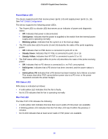
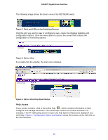
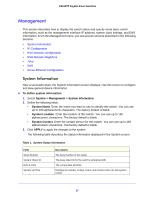
GS516TP Gigabit Smart Switches Management This section describes how to display the switch status and specify some basic switch information, such as the management interface IP address, system clock settings, and DNS information. From the Management menu, you can access screens described in the following sections: • System Information • IP Configuration • IPv6 Network Configuration • IPv6 Network Neighbors • Time • DNS • Green Ethernet Configuration System Information After a successful login, the System Information screen displays. Use this screen to configure and view general device information. To define system information: 1. Select System > Management > System Information. 2. Define the following fields: • System Name. Enter the name you want to use to identify this switch. You can use up to 160 alphanumeric characters. The factory default is blank. • System Location. Enter the location of this switch. You can use up to 160 alphanumeric characters. The factory default is blank. • System Contact. Enter the contact person for this switch. You can use up to 160 alphanumeric characters. The factory default is blank. 3. Click APPLY to apply the changes to the system. The following table describes the status information displayed in the System screen. Table 1. System Status Information Field Serial Number System Object ID Date & Time System Up Time Description The serial number of the switch. The base object ID for the switch's enterprise MIB. The current date and time. Displays the number of days, hours, and minutes since the last system restart. 27
-
 1
1 -
2
-
3
-
4
-
5
-
6
-
7
-
8
-
9
-
10
-
11
-
12
-
13
-
14
-
15
-
16
-
17
-
18
-
19
-
20
-
21
-
 22
22 -
 23
23 -
 24
24 -
 25
25 -
 26
26 -
 27
27 -
 28
28 -
 29
29 -
 30
30 -
 31
31 -
 32
32 -
33
-
34
-
35
-
36
-
37
-
38
-
39
-
40
-
41
-
42
-
43
-
44
-
45
-
46
-
47
-
48
-
49
-
50
-
51
-
52
-
53
-
54
-
55
-
56
-
57
-
58
-
59
-
60
-
61
-
62
-
63
-
64
-
65
-
66
-
67
-
68
-
69
-
70
-
71
-
72
-
73
-
74
-
75
-
76
-
77
-
78
-
79
-
80
-
81
-
82
-
83
-
84
-
85
-
86
-
87
-
88
-
89
-
90
-
91
-
92
-
93
-
94
-
95
-
96
-
97
-
98
-
99
-
100
-
101
-
102
-
103
-
104
-
105
-
106
-
107
-
108
-
109
-
110
-
111
-
112
-
113
-
114
-
115
-
116
-
117
-
118
-
119
-
120
-
121
-
122
-
123
-
124
-
125
-
126
-
127
-
128
-
129
-
130
-
131
-
132
-
133
-
134
-
135
-
136
-
137
-
138
-
139
-
140
-
141
-
142
-
143
-
144
-
145
-
146
-
147
-
148
-
149
-
150
-
151
-
152
-
153
-
154
-
155
-
156
-
157
-
158
-
159
-
160
-
161
-
162
-
163
-
164
-
165
-
166
-
167
-
168
-
169
-
170
-
171
-
172
-
173
-
174
-
175
-
176
-
177
-
178
-
179
-
180
-
181
-
182
-
183
-
184
-
185
-
186
-
187
-
188
-
189
-
190
-
191
-
192
-
193
-
194
-
195
-
196
-
197
-
198
-
199
-
200
-
201
-
202
-
203
-
204
-
205
-
206
-
207
-
208
 |
 |
