Netgear GS516TP Software Administration Manual - Page 22
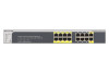
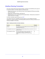
Power/Status LED, FAN Status LED, Max PoE LED, Solid green, Blinking yellow, Steady Green
 |
View all Netgear GS516TP manuals
Add to My Manuals
Save this manual to your list of manuals |
Page 22 highlights
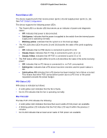
GS516TP Gigabit Smart Switches Power/Status LED The device supports ports that receive power (ports 1-8) and supply power (ports 15, 16). See PoE Global Configuration The device supports the following power LEDs. • The Power LED is a bicolor LED that serves as an indicator of power and diagnostic status: • Off. Indicates that power is disconnected. • Solid green. Indicates that the power is supplied to the switch from the internal power supply and is operating normally. • Blinking yellow .Indicates that the system is in the boot-up stage. • The PD LEDs (two LEDs for ports 15 and 16) describe the state of the ports supplying power: • Off. Indicates that no PSE device is connected to ports 15 or 16. • Steady Green. Indicates that AT PSE is connected to ports 15 or 16. • Steady Yellow. Indicates that AF PSE is connected to ports 15 or 16. • The PoE status LEDs (eight LEDs for ports 1-8) describes the state of the ports receiving power: • Off. Indicates that no PD device is connected (i.e. no PoE consumption). • Solid green. Indicates that a PD device has been inserted, and the power status is OK. • Solid yellow. PD Indicates that a PD device has been inserted, but a failure occurred This means that either PSE cannot deliver power due to a PD error or the power requested exceeds the power budget. FAN Status LED FAN status is indicated as follows: • A solid yellow LED indicates that the fan is faulty. • No lit LED indicates that the fan is operating normally. Max PoE LED The Max PoE LED indicates the following: • A solid yellow LED indicates that less than seven watts of PoE power are available. • A blinking yellow LED indicates that the PoE Max LED was lit within the previous 2 minutes. • No lit LED indicates that at least seven watts of PoE power are available. 22
-
 1
1 -
2
-
3
-
4
-
5
-
6
-
7
-
8
-
9
-
10
-
11
-
12
-
13
-
14
-
15
-
16
-
 17
17 -
 18
18 -
 19
19 -
 20
20 -
 21
21 -
 22
22 -
 23
23 -
 24
24 -
 25
25 -
 26
26 -
 27
27 -
28
-
29
-
30
-
31
-
32
-
33
-
34
-
35
-
36
-
37
-
38
-
39
-
40
-
41
-
42
-
43
-
44
-
45
-
46
-
47
-
48
-
49
-
50
-
51
-
52
-
53
-
54
-
55
-
56
-
57
-
58
-
59
-
60
-
61
-
62
-
63
-
64
-
65
-
66
-
67
-
68
-
69
-
70
-
71
-
72
-
73
-
74
-
75
-
76
-
77
-
78
-
79
-
80
-
81
-
82
-
83
-
84
-
85
-
86
-
87
-
88
-
89
-
90
-
91
-
92
-
93
-
94
-
95
-
96
-
97
-
98
-
99
-
100
-
101
-
102
-
103
-
104
-
105
-
106
-
107
-
108
-
109
-
110
-
111
-
112
-
113
-
114
-
115
-
116
-
117
-
118
-
119
-
120
-
121
-
122
-
123
-
124
-
125
-
126
-
127
-
128
-
129
-
130
-
131
-
132
-
133
-
134
-
135
-
136
-
137
-
138
-
139
-
140
-
141
-
142
-
143
-
144
-
145
-
146
-
147
-
148
-
149
-
150
-
151
-
152
-
153
-
154
-
155
-
156
-
157
-
158
-
159
-
160
-
161
-
162
-
163
-
164
-
165
-
166
-
167
-
168
-
169
-
170
-
171
-
172
-
173
-
174
-
175
-
176
-
177
-
178
-
179
-
180
-
181
-
182
-
183
-
184
-
185
-
186
-
187
-
188
-
189
-
190
-
191
-
192
-
193
-
194
-
195
-
196
-
197
-
198
-
199
-
200
-
201
-
202
-
203
-
204
-
205
-
206
-
207
-
208
 |
 |
