Netgear GS516TP Software Administration Manual - Page 21
Configuration and Status Options, Device View, System > Device View
 |
View all Netgear GS516TP manuals
Add to My Manuals
Save this manual to your list of manuals |
Page 21 highlights
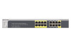
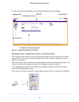
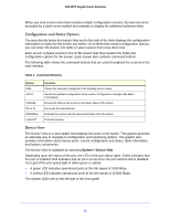
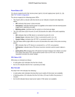
GS516TP Gigabit Smart Switches When you click a menu item that includes multiple configuration screens, the item becomes preceded by a down arrow symbol and expands to display the additional submenu links. Configuration and Status Options The area directly below the feature links and to the right of the links displays the configuration information or status for the screen you select. On screens that contain configuration options, you can enter information into fields or select options from drop-down lists. Each screen contains access to the HTML-based help that explains the fields and configuration options for the screen. Each screen also contains command buttons. The following table shows the command buttons that are used throughout the screens in the web interface. Table 1. Command Buttons Button ADD APPLY CANCEL DELETE REFRESH LOGOUT Function Places the new item configured in the heading row of a table. Sends the updated configuration to the switch. Configuration changes take effect immediately. Resets the data on the screen to the latest value of the switch. Removes the selected item. Reloads the screen with the latest information from the device. Ends the session. Device View The Device View is a Java applet that displays the ports on the switch. This graphic provides an alternate way to navigate to configuration and monitoring options. The graphic also provides information about device ports, current configuration and status, table information, and feature components. The Device View is available by selecting System > Device View. Depending upon the status of the port, the LED of the port status lights. Green indicates that the port is enabled. Red indicates that an error occurred on the port and the link is disabled. The LED of the port speed light in either green or yellow. • A green LED indicates operational ports at the link speed of 1000 Mbps. • A yellow LED indicates operational ports at the link speed of 10/100 Mbps. The system LEDs are on the left side of the front panel. 21
-
 1
1 -
2
-
3
-
4
-
5
-
6
-
7
-
8
-
9
-
10
-
11
-
12
-
13
-
14
-
15
-
 16
16 -
 17
17 -
 18
18 -
 19
19 -
 20
20 -
 21
21 -
 22
22 -
 23
23 -
 24
24 -
 25
25 -
 26
26 -
27
-
28
-
29
-
30
-
31
-
32
-
33
-
34
-
35
-
36
-
37
-
38
-
39
-
40
-
41
-
42
-
43
-
44
-
45
-
46
-
47
-
48
-
49
-
50
-
51
-
52
-
53
-
54
-
55
-
56
-
57
-
58
-
59
-
60
-
61
-
62
-
63
-
64
-
65
-
66
-
67
-
68
-
69
-
70
-
71
-
72
-
73
-
74
-
75
-
76
-
77
-
78
-
79
-
80
-
81
-
82
-
83
-
84
-
85
-
86
-
87
-
88
-
89
-
90
-
91
-
92
-
93
-
94
-
95
-
96
-
97
-
98
-
99
-
100
-
101
-
102
-
103
-
104
-
105
-
106
-
107
-
108
-
109
-
110
-
111
-
112
-
113
-
114
-
115
-
116
-
117
-
118
-
119
-
120
-
121
-
122
-
123
-
124
-
125
-
126
-
127
-
128
-
129
-
130
-
131
-
132
-
133
-
134
-
135
-
136
-
137
-
138
-
139
-
140
-
141
-
142
-
143
-
144
-
145
-
146
-
147
-
148
-
149
-
150
-
151
-
152
-
153
-
154
-
155
-
156
-
157
-
158
-
159
-
160
-
161
-
162
-
163
-
164
-
165
-
166
-
167
-
168
-
169
-
170
-
171
-
172
-
173
-
174
-
175
-
176
-
177
-
178
-
179
-
180
-
181
-
182
-
183
-
184
-
185
-
186
-
187
-
188
-
189
-
190
-
191
-
192
-
193
-
194
-
195
-
196
-
197
-
198
-
199
-
200
-
201
-
202
-
203
-
204
-
205
-
206
-
207
-
208
 |
 |
