Netgear GS516TP Software Administration Manual - Page 197
Sample MSTP Configuration, Configuration Table a VLAN ID to MSTID mapping
 |
View all Netgear GS516TP manuals
Add to My Manuals
Save this manual to your list of manuals |
Page 197 highlights
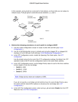
GS516TP Gigabit Smart Switches receive and transmit MSTP BPDUs. The MST configuration identifier has the following components: 1. Configuration identifier format selector 2. Configuration name 3. Configuration revision level 4. Configuration digest: 16-byte signature of type HMAC-MD5 created from the MST Configuration Table (a VLAN ID to MSTID mapping) As there are multiple instances of spanning tree, there is an MSTP state maintained on a per-port, per-instance basis (or on a per port, per VLAN basis, as any VLAN can be in only one MSTI or CIST). For example, port A can be forwarding for example 1 while discarding for example 2. The port states have changed since IEEE 802.1D specification. To support multiple spanning trees, an MSTP bridge has to be configured with an unambiguous assignment of VLAN IDs (VIDs) to spanning trees. This is achieved by: 1. Ensuring that the allocation of VIDs to FIDs is unambiguous. 2. Ensuring that each FID supported by the bridge is allocated to exactly one spanning tree instance. The combination of VID to FID and then FID to MSTI allocation defines a mapping of VIDs to spanning tree instances, represented by the MST Configuration table. With this allocation, every VLAN is assigned to one and only one MSTI. The CIST is also an instance of spanning tree with an MSTID of 0. An instance might occur that has no VIDs allocated to it, but every VLAN must be allocated to one of the other instances of spanning tree. The portion of the active topology of the network that connects any two bridges in the same MST region traverses only MST bridges and LANs in that region, and never bridges of any kind outside the region. In other words connectivity within the region is independent of external connectivity. Sample MSTP Configuration This example shows how to create an MSTP instance from the switch. The sample network has three different switches that serve different locations in the network. 197
-
 1
1 -
2
-
3
-
4
-
5
-
6
-
7
-
8
-
9
-
10
-
11
-
12
-
13
-
14
-
15
-
16
-
17
-
18
-
19
-
20
-
21
-
22
-
23
-
24
-
25
-
26
-
27
-
28
-
29
-
30
-
31
-
32
-
33
-
34
-
35
-
36
-
37
-
38
-
39
-
40
-
41
-
42
-
43
-
44
-
45
-
46
-
47
-
48
-
49
-
50
-
51
-
52
-
53
-
54
-
55
-
56
-
57
-
58
-
59
-
60
-
61
-
62
-
63
-
64
-
65
-
66
-
67
-
68
-
69
-
70
-
71
-
72
-
73
-
74
-
75
-
76
-
77
-
78
-
79
-
80
-
81
-
82
-
83
-
84
-
85
-
86
-
87
-
88
-
89
-
90
-
91
-
92
-
93
-
94
-
95
-
96
-
97
-
98
-
99
-
100
-
101
-
102
-
103
-
104
-
105
-
106
-
107
-
108
-
109
-
110
-
111
-
112
-
113
-
114
-
115
-
116
-
117
-
118
-
119
-
120
-
121
-
122
-
123
-
124
-
125
-
126
-
127
-
128
-
129
-
130
-
131
-
132
-
133
-
134
-
135
-
136
-
137
-
138
-
139
-
140
-
141
-
142
-
143
-
144
-
145
-
146
-
147
-
148
-
149
-
150
-
151
-
152
-
153
-
154
-
155
-
156
-
157
-
158
-
159
-
160
-
161
-
162
-
163
-
164
-
165
-
166
-
167
-
168
-
169
-
170
-
171
-
172
-
173
-
174
-
175
-
176
-
177
-
178
-
179
-
180
-
181
-
182
-
183
-
184
-
185
-
186
-
187
-
188
-
189
-
190
-
191
-
 192
192 -
 193
193 -
 194
194 -
 195
195 -
 196
196 -
 197
197 -
 198
198 -
 199
199 -
 200
200 -
 201
201 -
 202
202 -
203
-
204
-
205
-
206
-
207
-
208
 |
 |
