Netgear GS516TP Software Administration Manual - Page 137
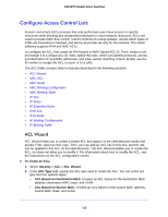
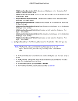
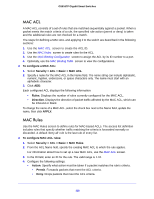
APPLY, To add a rule to the ACL, select the check box next to the ACL, then click
 |
View all Netgear GS516TP manuals
Add to My Manuals
Save this manual to your list of manuals |
Page 137 highlights
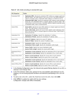
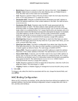
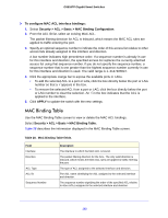
GS516TP Gigabit Smart Switches Table 27. ACL fields according to selected ACL type. ACL Based on Fields Destination MAC • Destination MAC. Specify the destination MAC address to compare against an ethernet frame. The valid format is (xx:xx:xx:xx:xx:xx). The BPDU keyword might be specified using a destination MAC address of 01:80:C2:xx:xx:xx. • Destination MAC Mask. specify the destination MAC address mask specifying which bits in the destination MAC to compare against an ethernet frame. The valid format is (xx:xx:xx:xx:xx:xx). The BPDU keyword might be specified using a destination MAC mask of 00:00:00:ff:ff:ff. Source MAC • Source MAC. Specify the source MAC address to compare against an ethernet frame. The valid format is (xx:xx:xx:xx:xx:xx). • Source MAC Mask. Specify the source MAC address mask specifying which bits in the source MAC to compare against an ethernet frame. Valid format is (xx:xx:xx:xx:xx:xx). Destination IPv4 • Destination IP Address. Specify the destination IP address. • Destination IP Mask. Specify the destination IP address mask. Source IPv4 • Source IP Address. Specify the source IP address. • Source IP Mask. Specify the source IP address mask. Destination IPv6 • Destination Prefix. Specify the destination prefix. • Destination Prefix Length. Specify the destination prefix length. Source IPv6 • Source Prefix. Specify the source destination prefix. • Source Prefix Length. Specify the source prefix length. Destination IPv4 L4 Port • Destination L4 port (protocol). Specify the destination IPv4 L4 port protocol. • Destination L4 port (value). Specify the destination IPv4 L4 port value. Source IPv4 L4 Port • Source L4 port (protocol). Specify the source IPv4 L4 port protocol. • Source L4 port (value). Specify the source IPv4 L4 port value. Destination IPv6 L4 Port • Destination L4 port (protocol). Specify the destination IPv6 L4 port protocol. • Destination L4 port (value). Specify the destination IPv6 L4 port value. Source IPv6 L4 Port • Source L4 port (protocol). Specify the source IPv6 L4 port protocol. • Source L4 port (value). Specify the source IPv6 L4 port value. 4. In the Binding Configuration area, the Inbound only packet filtering direction for an ACL is selected in the Direction field. 5. In the Port Selection Table area, specify the list of all available valid interfaces for ACL mapping. All non-routing physical interfaces and interfaces participating in the LAG are listed. 6. To add a rule to the ACL, select the check box next to the ACL, then click ADD. 7. Click APPLY to update the switch with the new settings. Configuration changes take effect immediately. 137
-
 1
1 -
2
-
3
-
4
-
5
-
6
-
7
-
8
-
9
-
10
-
11
-
12
-
13
-
14
-
15
-
16
-
17
-
18
-
19
-
20
-
21
-
22
-
23
-
24
-
25
-
26
-
27
-
28
-
29
-
30
-
31
-
32
-
33
-
34
-
35
-
36
-
37
-
38
-
39
-
40
-
41
-
42
-
43
-
44
-
45
-
46
-
47
-
48
-
49
-
50
-
51
-
52
-
53
-
54
-
55
-
56
-
57
-
58
-
59
-
60
-
61
-
62
-
63
-
64
-
65
-
66
-
67
-
68
-
69
-
70
-
71
-
72
-
73
-
74
-
75
-
76
-
77
-
78
-
79
-
80
-
81
-
82
-
83
-
84
-
85
-
86
-
87
-
88
-
89
-
90
-
91
-
92
-
93
-
94
-
95
-
96
-
97
-
98
-
99
-
100
-
101
-
102
-
103
-
104
-
105
-
106
-
107
-
108
-
109
-
110
-
111
-
112
-
113
-
114
-
115
-
116
-
117
-
118
-
119
-
120
-
121
-
122
-
123
-
124
-
125
-
126
-
127
-
128
-
129
-
130
-
131
-
 132
132 -
 133
133 -
 134
134 -
 135
135 -
 136
136 -
 137
137 -
 138
138 -
 139
139 -
 140
140 -
 141
141 -
 142
142 -
143
-
144
-
145
-
146
-
147
-
148
-
149
-
150
-
151
-
152
-
153
-
154
-
155
-
156
-
157
-
158
-
159
-
160
-
161
-
162
-
163
-
164
-
165
-
166
-
167
-
168
-
169
-
170
-
171
-
172
-
173
-
174
-
175
-
176
-
177
-
178
-
179
-
180
-
181
-
182
-
183
-
184
-
185
-
186
-
187
-
188
-
189
-
190
-
191
-
192
-
193
-
194
-
195
-
196
-
197
-
198
-
199
-
200
-
201
-
202
-
203
-
204
-
205
-
206
-
207
-
208
 |
 |
