Netgear GS516TP Software Administration Manual - Page 75
Rapid STP, MST Configuration, Switching > STP > Advanced > MST Configuration
 |
View all Netgear GS516TP manuals
Add to My Manuals
Save this manual to your list of manuals |
Page 75 highlights
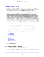
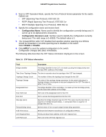
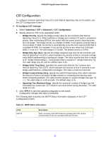
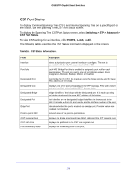
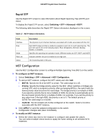
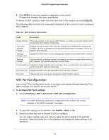
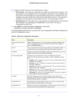
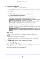
GS516TP Gigabit Smart Switches Rapid STP Use the Rapid STP screen to view information about Rapid Spanning Tree (RSTP) port status. To display the Rapid STP screen, select Switching > STP > Advanced > RSTP. The following table describes the Rapid STP Status information displayed on the screen. Table 17. RSTP Status Information. Field Interface Role Mode Fast Link Status Description The physical or port channel interfaces associated with VLANs associated with the CST. Each MST bridge port that is enabled is assigned a port role for each spanning tree. The port role can be one of the following values: Root, Designated, Alternate, Backup, Master, or Disabled. Specifies the spanning tree operation mode. Different modes are STP, RSTP, and MSTP. Indicates whether the port is enabled as an edge port. The forwarding state of this port. MST Configuration Use the MST Configuration screen to configure Multiple Spanning Tree (MST) on the switch. To configure an MST instance: 1. Select Switching > STP > Advanced > MST Configuration. 2. To add an MST instance, configure the MST values and click Add: • MST ID. Specify the ID of the MST to create. The valid range is 1-15. • Priority. Specify the bridge priority value for the MST. When switches or bridges are running STP, each is assigned a priority. After exchanging BPDUs, the switch with the lowest priority value becomes the root bridge. The bridge priority is a multiple of 4096. If you specify a priority that is not a multiple of 4096, the priority is automatically set to the next lowest priority that is a multiple of 4096. For example, if you set the priority to any value from 0 through 4095, the priority is set to 0. The default priority is 32768.The valid range is 0-61440. • VLAN ID. The list contains all VLANs configured on the switch. Select a VLAN to associate with the MST instance. 3. Click APPLY to send the updated configuration to the switch. Configuration changes take place immediately. To modify an MST instance: 1. Select the check box next to the instance to configure and update the values. You can select multiple check boxes to apply the same setting to all selected MTS instances. 75
-
 1
1 -
2
-
3
-
4
-
5
-
6
-
7
-
8
-
9
-
10
-
11
-
12
-
13
-
14
-
15
-
16
-
17
-
18
-
19
-
20
-
21
-
22
-
23
-
24
-
25
-
26
-
27
-
28
-
29
-
30
-
31
-
32
-
33
-
34
-
35
-
36
-
37
-
38
-
39
-
40
-
41
-
42
-
43
-
44
-
45
-
46
-
47
-
48
-
49
-
50
-
51
-
52
-
53
-
54
-
55
-
56
-
57
-
58
-
59
-
60
-
61
-
62
-
63
-
64
-
65
-
66
-
67
-
68
-
69
-
 70
70 -
 71
71 -
 72
72 -
 73
73 -
 74
74 -
 75
75 -
 76
76 -
 77
77 -
 78
78 -
 79
79 -
 80
80 -
81
-
82
-
83
-
84
-
85
-
86
-
87
-
88
-
89
-
90
-
91
-
92
-
93
-
94
-
95
-
96
-
97
-
98
-
99
-
100
-
101
-
102
-
103
-
104
-
105
-
106
-
107
-
108
-
109
-
110
-
111
-
112
-
113
-
114
-
115
-
116
-
117
-
118
-
119
-
120
-
121
-
122
-
123
-
124
-
125
-
126
-
127
-
128
-
129
-
130
-
131
-
132
-
133
-
134
-
135
-
136
-
137
-
138
-
139
-
140
-
141
-
142
-
143
-
144
-
145
-
146
-
147
-
148
-
149
-
150
-
151
-
152
-
153
-
154
-
155
-
156
-
157
-
158
-
159
-
160
-
161
-
162
-
163
-
164
-
165
-
166
-
167
-
168
-
169
-
170
-
171
-
172
-
173
-
174
-
175
-
176
-
177
-
178
-
179
-
180
-
181
-
182
-
183
-
184
-
185
-
186
-
187
-
188
-
189
-
190
-
191
-
192
-
193
-
194
-
195
-
196
-
197
-
198
-
199
-
200
-
201
-
202
-
203
-
204
-
205
-
206
-
207
-
208
 |
 |
